
GO DEEPER AND FIND THE MYSTERY IN THIS VOLKSWAGEN GOLF
How many times does a vehicle enter the repair facility with the most unusual faults and running behavior? How about when the faults change mid stream and point to a possible deep repair?
- The 2010 Golf with a 2.5L R5 arrived on a flat bed.
- The engine did start, however ran with what appeared to be multiple misfires with a stalling condition when cold.
- The throttle had to be “teased†to keep it running.
- When warmed to operating temperature, the Golf maintained idle.
First was the need to access the PR code and, using ElsaWin, narrow the specific model for repair information and electrical schematics. Sales code: 5K1 2S3
| Tools Used |
| VCDS with a 90 amp power supply |
| Heat gun, crimp and shrink connectors |
| Screen capturing software |
| Pen and paper and a simple camera |
The vehicle and customer history
A conscientious customer messaged the facility with information that one of their children purchased a 2010 Golf. The VW began to run poorly soon after it left a used car lot. The used car lot sales staff was not of any help and also made mention of the fact that some sales member had a brother of a cousin twice removed from humanity and had worked on the Golf that was owned by who knows who.
Day 1, the Golf arrived on a flat bed and it did start, but complained.
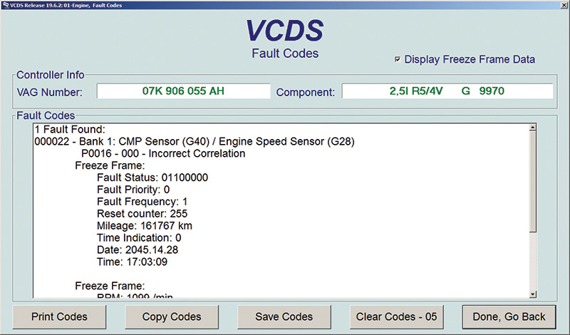
Capture the initial scan with VCDS and save it. In question are these primary faults with repeating freeze frames.
| Freeze Frame |
| RPM: 711 /min |
| Load: 46.3 percent |
| Speed: 0.0 km/h |
| Temperature: 89.0 degrees C |
| Temperature: 33.0 degrees C |
| Absolute Pres.: 960.0 mbar |
| Voltage: 13.716 V |
| 5 Faults Found: |
| 008568 – Bank 1; System Too Rich off Idle P2178 – 000 |
| 000768 – Random/Multiple Cylinder Misfire Detected P0300 – 000 |
| 000770 – Cylinder 2 P0302 – 000 – Misfire Detected |
| 000772 – Cylinder 4 P0304 – 000 – Misfire Detected |
| 000773 – Cylinder 5 P0305 – 000 – Misfire Detected |
| Readiness: 1110 0101 |

With the initial scan captured and saved, deleted the faults with KOEO and started the engine again. These identical faults returned multiple times.
Where to start
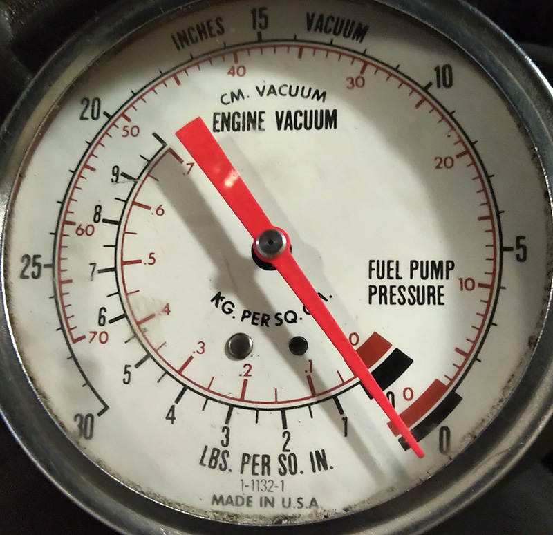
One simple yet quick test was with a vacuum gauge to ensure the crankcase ventilation system (PCV) was not damaged. The need was to ensure there was no internal vacuum leak. Remember the Jetta article with the damaged diaphragm on the valve cover? Go back and read that article.
The reading here was well within a normal range.
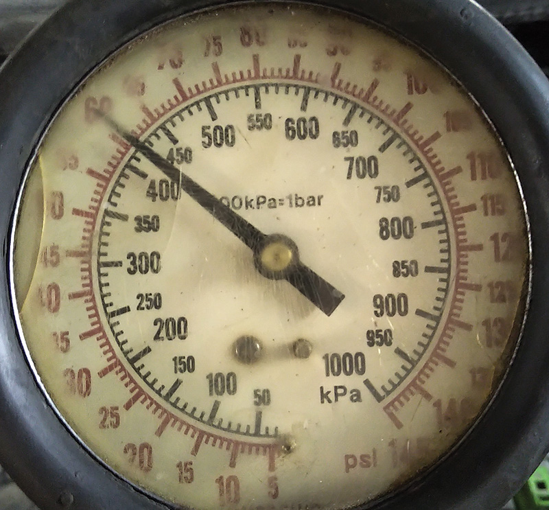
With that test in mind and passed while connected to the dipstick tube, the next test was to monitor the fuel pump pressure at the rail. That test passed as well and did not indicate a rich condition.
425 kPa (61 psi) is quite close to what was expected and the specification for this model is between 3.5 and 4.5 bar, or 51 to 65 psi (425 kPa = 4.25 bar).
Despite the recorded misfires, the engine appeared/sounded smooth with a total lack of power and definitely no torque.
Something seems off, what is it?
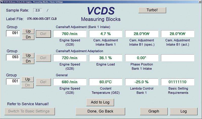
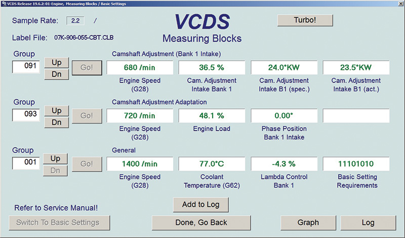
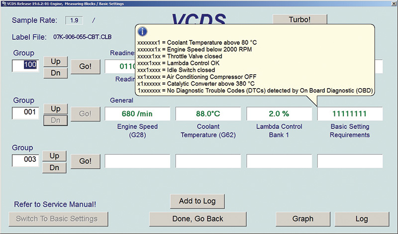
With VCDS there were a few anomalies with the engine running at idle. A few values are questionable. Three tests were of interest because of live values not close to where they should be. With the upper engine cover removed, the throttle body was definitely cleaned.
Viewing live data in Group 001, field 3 is Lambda Control Bank 1.
A value stuck at -25.0 percent was certainly not expected.
Lambda values explained
Negative Lambda values are an indication that the engine is running too rich.
The oxygen sensor is monitoring the value while the ECM is controlling the mixture towards lean by reducing the amount of injector ON (open) time.
Positive Lambda values are an indication the engine is running too lean.
The oxygen sensor is monitoring the value while the ECM is controlling the mixture towards rich by increasing the amount of injector OFF (closed) time.
Viewing live data in Group 002, field 3, Injection Pulse Width.
A value of 7.2 ms is quite fat/rich/wide with an ambient temperature of 19.0 degrees C at the intake temperature sensor and 60.0 degrees C at the coolant temperature sensor.
Viewing live data in Group 001, field 4, Basic Setting Requirements.
xxxxx1xx = Throttle Valve Closed
xxxx1xxx = Lambda Control OK
xxx1xxxx = Idle Switch Closed
During the first live tests, there were at least 3 digits of concern at idle. VCDS will generate a “pop up†if hovering over the field with more specific information. This vehicle generated all “0’s†in the noted explanation above.
The values matched an engine management system attempting to idle while opening the throttle slightly to maintain a rich running condition at:
Group 001, field 3 (Lambda -25.0 percent).
After these tests were recorded and saved, the engine was switched off again and the recorded faults were deleted. The engine was restarted multiple times, deleting the misfires at least twice more. This last time, everything changed dramatically on the next engine start.
000022 – Bank 1: CMP Sensor (G40) / Engine Speed Sensor (G28)
P0016 – 000 – Incorrect Correlation
| Freeze Frame | |
| RPM: 763 /min | Temperature: 23.0 degrees C |
| Load: 41.2 percent | Absolute Pres.: 970.0 mbar |
| Speed: 0.0 km/h | Voltage: 13.970 V |
| Temperature: 76.0 degrees C |
The misfires certainly didn’t return and this specific fault repeated numerous times. In one respect, this would appear that the upper and/or lower timing chain is out of alignment and could possibly explain why the ECM recorded multiple misfires with the “new and improved†P0016 – 000 – Incorrect Correlation.
A running shop test and trying to force the camshaft to advance with slight throttle bursts provided no changing results and the camshaft advance or retard data remained at “default†values. Basic settings also failed.
Day 2, this Golf has a story to tell.
These engines are well known for stretched chains, worn sliders and loose/leaking camshaft adjusters mounted on the intake cam.
If that was true, this Golf may have required some “internal surgery†and lots of hot coffee. So what was really going on with this poor running Golf?
Side note using VCDS
If for any reason a fault is recorded, even in history, live values will be at default because of how engine management attempts to keep the engine running. Any other adaptations such as basic settings will not work, will not engage, will not complete a test and in many cases will set related faults.
In this case, engine management would not allow any test to pass.
Tests were: Throttle adaptation, WOT adaptation and Intake Camshaft adaptation.
So what was found and what was the thinking?

First noticed was the bulky amount of thinned out silicone that was sealing the upper timing cover attached to the cylinder head (page one of the Neanderthals that should never have access to a silicone injection gun).
Second was that shiny new camshaft solenoid with the damaged harness connection and bent/damaged wires.
Next test, remove the solenoid
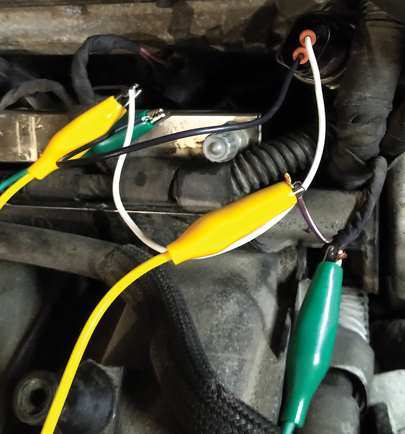
With a co-worker, the ignition key was cycled and some solenoid movement was observed while holding it. The first test was with battery power to engage the solenoid in the forward or reverse positions (switching the B plus and B minus) on the solenoid pins. A cleaning solution was used on the solenoid that directs oil to either side of the camshaft phaser (the advance or retard position). Test two was inserting a small air nozzle into the cylinder head to eject any debris outwards. With the fuel system disabled at test three, and with short starter bursts, any remaining debris was pushed into a waiting towel.
With two well fitting scavenged wires and quality jumper wires, a “quick connection†was added to the cut harness and, using a Dr. Frankenstein quote, “it’s alive!â€
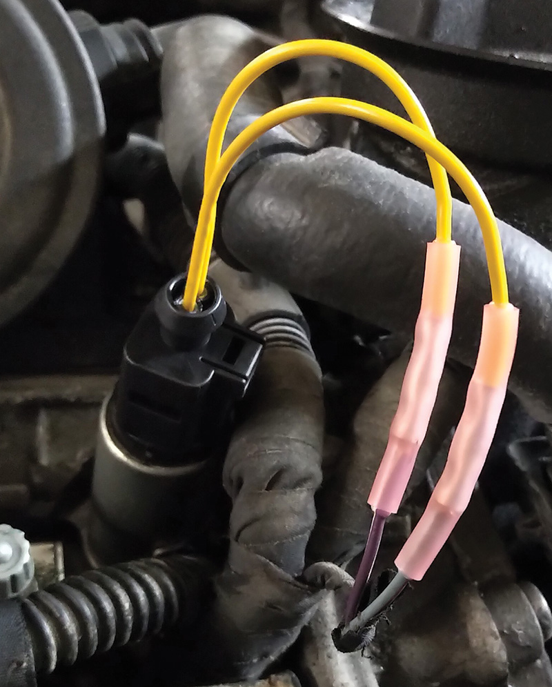
Now to replace the wires and connector shell

A picture does hold a great value and as the saying goes, “a picture is indeed worth a thousand words.†What are the possibilities that the dealer gets it wrong three times?
With the replacement shell (1J0 973 702) and personal stock of the correct diameter wires with crimp/shrink connections, the final test is the three basic settings that are required to have the engine run in factory condition.
Using the crimp and shrink connections and making sure the harness is taped/tied away from the engine cover, we continued with Basic Settings.
VCDS was used to access Basic Settings and follow the menu for:
Throttle adaptation, WOT adaptation, and Intake Camshaft adaptation.
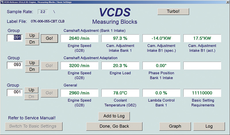
These three tests passed and no fault codes were recorded, so the next step was finish and save all data when the readiness monitors passed.
Finally time to perform a mixed city and highway road test and recheck for faults.
Look at the differences in Group 001, field 4, Basic Setting Requirement. Notice the changes applying the throttle and how the scan tool displays the “requirements†the engine management system is reading.
Note: Changes in rpm in these screens are because VCDS accessed each group one at a time and displayed the data in each group on the screen. Following are the readings for the next group and that data will be displayed within the correct groups and so on. The process starts again and is looped continuously.
Final test and proof the ECM is in control
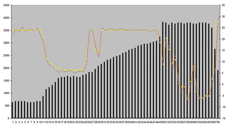
With VCDS, the choice was to also use the “LOG†feature and capture groups 091, 093 and 094.
The recorded log lasted approximately 30 seconds. While recording with the transmission in Park from idle, the throttle was pressed and held for seconds at the 1500, 2000, 2500, 3000, 3500, and until “the rev limiter†was noticed and let throttle off. At idle, the log file was saved.
Using Microsoft Excel, only the columns in group 091 were chosen in this example to highlight the transition from low to high rpm for 30 seconds.
The choice for the example was fields (1), (3) and (4).
Respectively:
- (1) is rpm in the black vertical lines.
- (3) is Cam Adjustment Specified in crank angle degrees colored in red.
- (4) is Cam Adjustment Actual in crank angle degrees colored in yellow.
Attempt this interesting way of graphing with combination of groups while mixing multiple fields.
The data plot is another feature that provides proof that the engine management system is in complete control and the symphony is in total harmony.
This particular plot was accomplished in the service bay but the recording can be performed with similar or other tests while the vehicle is in motion.
Use these key words to find a reputable supplier with the correct connections/tools:
“Crimp and shrink connectorsâ€
“VW Connector Shell and replacement wires with sealsâ€
“Heat/shrink toolâ€
At the end of this episode, sometimes the faults are real and there were multiple misfires recorded. With a warmer engine and possibly dislodged debris with silicone, the new fault needed a critical look at what was touched before. Small data anomalies did lead to an internal valve timing defect. The key is to keep reading the data and recognize the difference between what is real/current/correct and a symphony with a real bad actor.
Take the time to go deeper and solve the mystery.


0 Comments