
This topic is covered in a short series. Parts 1 and 2 will discuss how to find a possible parasite within a scan and how to measure a parasite after repairs.
Part 1: Alarm Failure
| Tools Used |
| Laptop running VCDS |
| Various ranging 40, 60 and 200 amp clamp testing |
| 90 amp power supply with DLC breakout box |
| Sperry Smartmeter, Fluke multimeter, and Android device |
| Screen capturing and screen (video) recording software |
| Slack tube manometer and purpose made test cap |
| PDF printer to save documents and schematics |
| Pen, paper, camera, and 20:1 jewelers loupe for close up photos |
A well respected body shop owner asked if a 2006 Audi A6 Quattro could be looked at and when it might be convenient to do so. The best answer was, “I’ll come and get it; just leave it with me though.â€
It was picked up, driven to the “Lab†and left in the parking area for a short while. What were the chances this A6 (with the statement above) in the course of a week, had a completely discharged battery?
Discharged by how much?
The battery was so dead that the remotes didn’t operate, so the bladed key was used to open the driver’s door and opened the trunk to access the battery. A fully charged jump pack was attached and oddly, the alarm was set, the lights flashed without the alarm sounder making any noise. The key was used in the ignition to disable the “quiet alarm flashing lamps.â€
One caution to note
Any model that has an energy management system should have a fully charged jump pack attached and remain connected for at least 30 minutes to hopefully equalize the battery voltage and later start the engine.
With these models experiencing a dead battery, the best advice is to scan the entire network and save those results immediately. Be aware that most of the controllers will record battery B+ faults. Pay close attention to the faults recorded for address 61 Battery Regulation.
Before moving the vehicle, ensure the battery pack is securely attached and safe before moving these vehicles.
Another term used is “Energy Management.†So what was happening with the built in alarm module? There will be more details after this part is completed.
Scanned Data – Shortened Version |
|
| Address 46: Central Conv. | Labels:. 4F0-910-289.lbl |
| Part No SW: 4F0 910 289 G | HW: 4F0 907 289 G |
| Component: Komfortgeraet | H18 0120 |
| Revision: 01200018 | Serial number: 01004338590000 |
| Coding: 4618301 | |
| Shop #: WSC 93117 999 84391 | |
| VCID: 2E53FBC6B92AC7F6A9-807A | |
| Subsystem 1 – Component: Sounder No Answer | |
2 Faults Found |
|
| 02071 – Local Databus | 012 – Electrical Fault in Circuit |
| Mileage: 131929 km, Date: 2005.02.03, Time: 07:21:44 | |
| 01134 – Alarm Horn (H12) 004 – No Signal/Communication | |
| It arrived with 131980 km, battery replacement reset the default date/time. | |
Surgical procedure
This model was later started after the initial scan was saved. In the “Lab†and attaching the 90 amp power supply to the “new previously replaced†battery, offered one hint. There was an earlier article about another “Tips and Tricks with a 2008 Audi A6 3.2L no crank/no start†that was remembered.
What was discovered?
With previous histories of VW and Audi LIN alarms, the plenum cover was lifted and inspected (noticing the green debris similar to pollen), it looked like water was captured within the plenum under the windshield. We were all amazed about the amount of captured water from the area.
The water and debris left a distinct water line across the entire region of the plenum. Simply, the LIN Sounder was the parasite on the network.
What about the battery?
It certainly wasn’t an OEM brand, and there will be more details later on with that scenario. With a camera, we identified and noted everything for future reference.
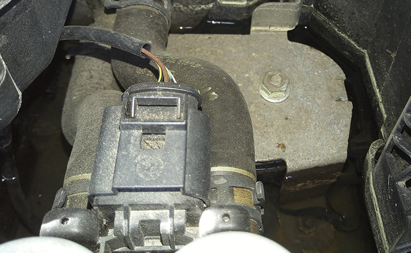
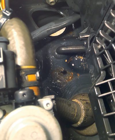
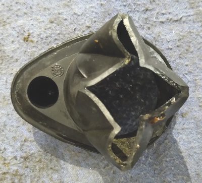
While amazed about the water, an interest was the plugged rubber drain with “soggy decomposing material.†The plenum contains items such as the brake booster, master cylinder, wiper motor, access panels to electronic controls, wiring harness, ground connections, etc. etc.
The two illustrations indicate the location of the body drain under the LIN horn sounder. Since the drain itself was completely plugged; we opted to trim the closed portions to allow more water and debris to escape. We washed out the remaining debris and reinstalled the rubber drain when complete. Double checked were any ground connections or water intrusions within the plenum area.
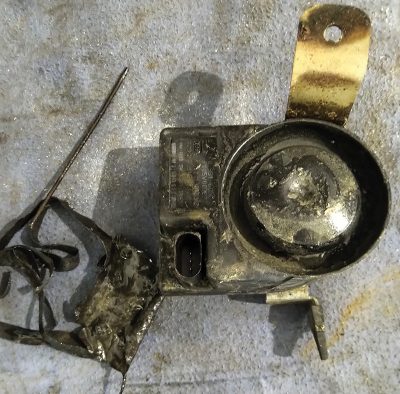
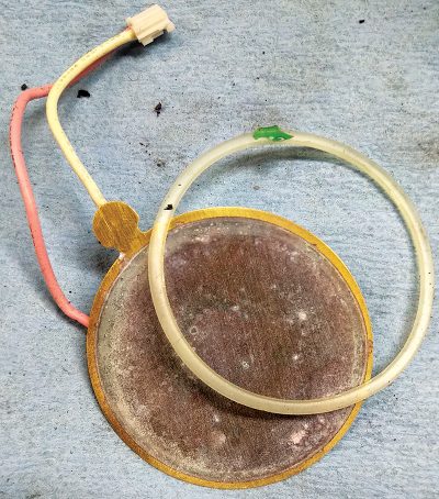
Now that the LIN sounder was in hand and having a bad day, we opened this bad actor to see what made it tick. With a good quality razor knife (wear gloves, I did cut myself) slid the blade to open/scrape the cover at its seam.
This element is a Piezo speaker. The LIN sounder will activate the speaker with a “chirp†when locking the A6 with the remote, or scream when the A6 is opened without a key or, if the A6 is tilted “stolen or towed,†the systems are monitored for theft or intrusion. Applying battery power to the element made it sound like a strangled chicken. No offense to chickens!
The replacement is VWC Siren, part number 1K0951605F.
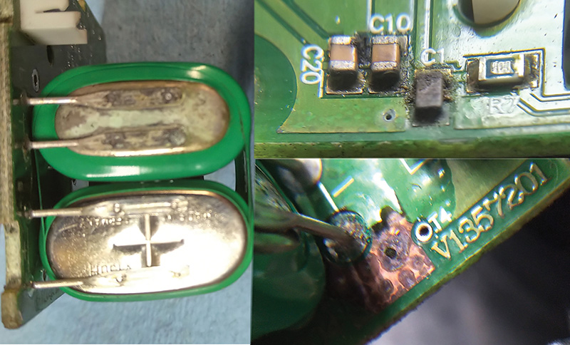
The battery is a VARTA version 2×3.6V 140 mAh Ni-MH.
De-soldering the battery provided a near dead voltage reading.
What was learned?
The scan was nearly identical to the past article “Tips and Tricks with a 2008 Audi A6 3.2L no crank/no start†when reading that recorded incident more that a year ago. The LIN horn in both scans provided faults, did not operate and in that worst scenario, would not start the 2008 A6.
In this particular incident, the parasite killed one battery and depleted the replacement in a short space of time. Part 2 will offer a few insights about non OEM batteries and the behavior of the energy management system.
Part 2: Alarm Parasite
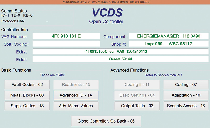
Capturing the initial scan also produced faults within address 61 (Energy Management) as mentioned in the first part of this article. The primary scan and subsequent scans tell an interesting story.
Scanned Data – Shortened Version | |
| Address 61: Battery Regul. | Labels\User: 4F0-910-181-E.lbl |
| Part No SW: 4F0 910 181 E | HW: 4F0 915 181 A |
| Component: ENERGIEMANAGER H12 0490 | |
| Revision: 00000000 | Serial number: 00000000037497 |
| Shop #: WSC 93117 999 59144 | |
| Subsystem 1 – Part No: 4F0 915 105 C | |
| Component: von VA0 1504240113 | |
| Coding: 344630393135313035432056413031353034323430313133 | |
| Shop #: WSC 00000 384 00290 | |
4 Faults Found | |
| 02273 | Quiescent Current Stage 2 000 – – – Intermittent |
| 02276 | Quiescent Current Stage 5 000 – – – Intermittent |
| 02274 | Quiescent Current Stage 3 000 – – – Intermittent |
| 02277 | Quiescent Current Stage 6 000 – – – Intermittent |
| Within this scan, the mileage is still recorded at 131974 km but the current mileage on the odometer is 131980 km. | |
| Each stage however recorded different time logs. | |
| Quiescent Current Stage 2 | Time: 11:39:26 |
| Quiescent Current Stage 5 | Time: 11:40:42 |
| Quiescent Current Stage 3 | Time: 11:40:52 |
| Quiescent Current Stage 6 | Time: 11:41:02 |
| These recorded intervals happened very quickly and within seconds, to make any logical sense. | |
Quiescent Current Stage Descriptions
Stage 1. CAN Convenience loads are deactivated.
Stage 2. Additional CAN Convenience load with Infotainment System restrictions.
Stage 3. Initialization of KEY ON “closed circuit†current reduction.
Stage 4. Deactivation in this stage can only be performed by a VAG style scan tool. The J644 module can not independently initiate this program.
Stage 5. Deactivation of the auxiliary heater.
Stage 6. Reduction of bus system wake-up.
What could have happened?
The battery was previously replaced and if past articles are an indication, the “VW Touareg – As If†topic becomes the indicator with the same body shop that replaced this A6 battery. Déjà vu strikes again!
The bet was that the plenum was filled with water on and off, dependent on weather. The LIN sounder failed and was likely the “parasite over time.â€
This scenario must have repeated itself multiple times until someone decided to replace the battery (resetting the clock and time), or this parasite was so aggressive that everything was reset every time the parasite was active.
I’ll believe in the and/or scenario.
The correct procedure to replace a battery
1a) If a suspect battery is defective, allow the network to enter sleep mode.
1b) If a suspect battery requires immediate replacement, attach a jump pack to the battery cables to keep the systems alive.
1c) If there is no immediate requirement and the systems have entered sleep mode, attach a DLC battery pack when in sleep mode.
2) Opening or closing any door, hood or trunk will activate the network!
3) If unsure about connections, request a second technician for help.
Battery registration
In the majority of cases, aftermarket batteries are installed that DO NOT have the correct serial number or data to incorporate/register the battery. This may cause future Energy Management issues.
In that case, choose a battery that is equal to or better than the original battery. Not all VW or Audi models with energy management systems have the ability to input new data compared to the OEM battery versions.
More on this later but let’s move on to a suspect parasite.
Special Notes
If for any reason battery power was disturbed, many control modules will require some type of basic settings or time/date settings within the MMI or instrument cluster. Examples may be throttle body adaptations, HVAC adaptations, power seat and memory seat adaptations and, in the worst case, remote fob and radio/navigation adaptations, including smart phone apps.
What does a parasite look like?
Many well trained technicians have accurate tools such as a multimeter and an amp clamp(s). Those tools do measure the total parasite and are dependent on the battery B- connection. The most accurate connection is with ONE ground connection to a clean body connection. A double connected battery B- connection is not accurate.
The Path of Least Resistance
Electrical energy will always take low resistance paths and will include the one with least resistance. Electrical energy will also take every other path available to it.
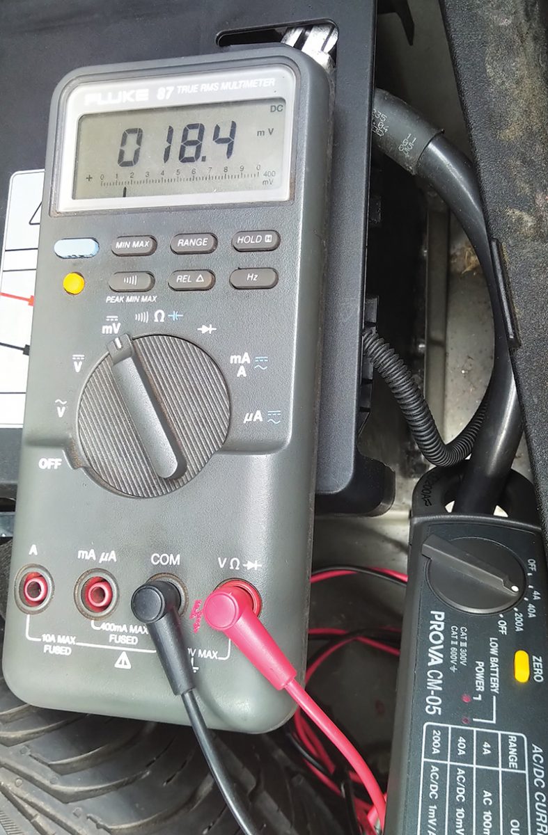
The following images allow for a parasite to be measured and, using two tools, offer the images in different forms. Both tests were with the everyday use multimeter and another simplistic meter that graphs the parasite over time.
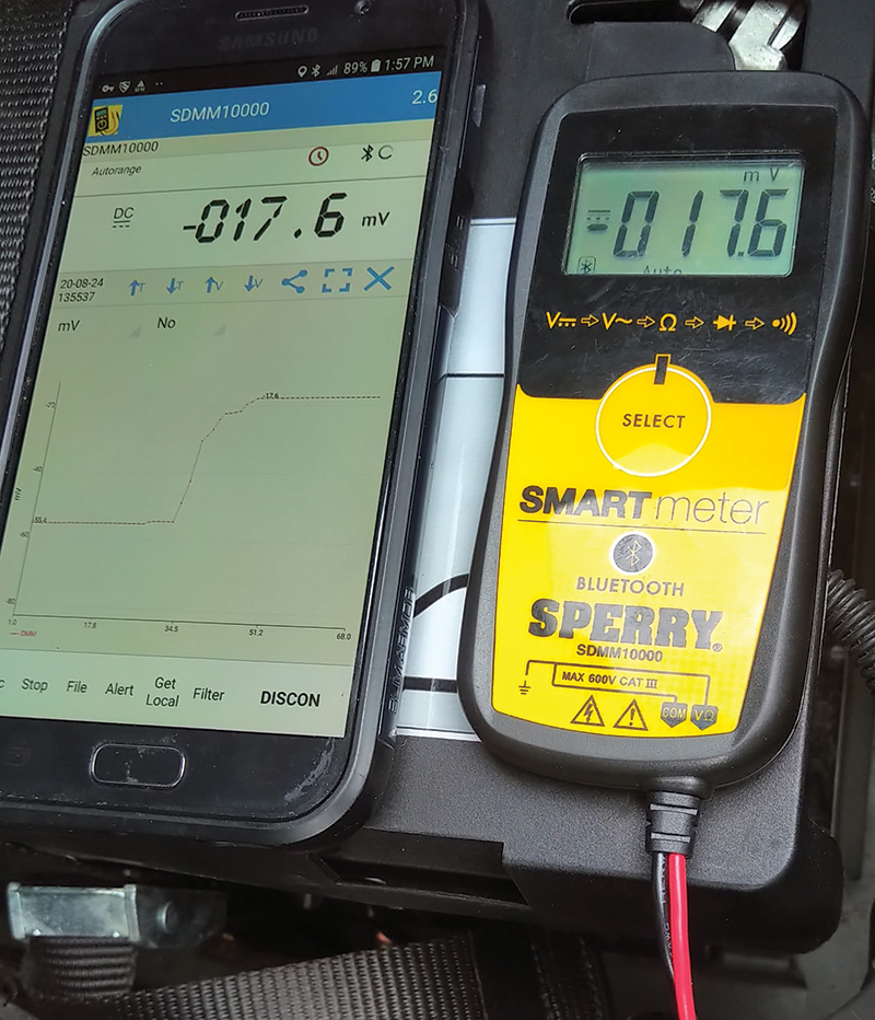
This second/new meter sent data via Bluetooth to an Android or IOS device. The graphing display was an eye opener but it was the simplicity that was appreciated without the long “babysitting†scenario. The device was left near my coffee cup for instant viewing.
Now imagine sending the “baby sitting†graph to a smart TV mounted on the wall of the service bay.
Meter A reads the amperage draw except in the wrong direction. Meter A reads the amperage on the positive scale. This model has only ONE ground connection. Correctly orient the direction of the amp clamp.
Meter B amp clamp is oriented correctly and reads the amperage draw on the negative scale. With the Meter B reading the added Android device connection can be moved about 30 feet away.
Remember
Every time one or more doors, hood, or trunk is opened, the network becomes active. That will also include activity when closing, removing a key, proximity key location, and that elusive, “glove box door.â€
Remember Also
Have a good look at the amp clamps that are in use, orient the amp clamp correctly to monitor the amperage flow in the correct direction.
If using this Sperry test device, (or similar) don’t close the hood or trunk because the Bluetooth connection will be inactive/blocked. Only latch it but again, yours truly awakened the parasite!!
As with any application, choose the best and safest method to monitor the parasite over time. The next graph is in real time (open and close LF door).
Numerous amp clamps were tested, the preference is the medium opening jaw the PROVA CM-05 offers with a scale of 40 amps or 200 amps for parasites.
The remaining clamps tested are equally accurate, many having smaller opening jaws or quite large as in the 650 amp version.
As with many amp clamps on the market, choose one or more amp clamps for their sensitivity and paying attention to the current test that will fit tools such as multimeters and oscilloscopes.
There will be added details in following articles for the Sperry Bluetooth meter with the adjustments and recording over time.
The following image is of the non OEM fully charged and tested battery. The A6 scan was clean, all adaptations were set with a new LIN Sounder installed.
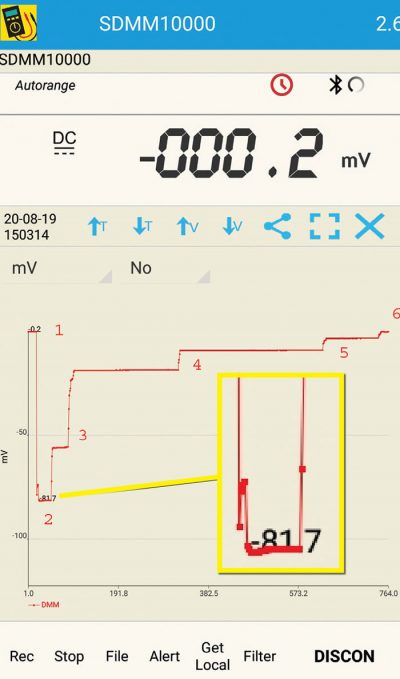
The image follows many models that have modern networks, graphing sleep mode. Be aware, not all follow the exact command sets for sleep mode and is dependant on the installed equipment.
What does the image indicate?
- The vehicle already in sleep mode with the Android and amp clamp attached to the B- cable. Trunk and hood have been opened for some time.
- The moment the driver’s door was opened and closed
Note: An added image bordered in yellow was created and placed to display that moment one door was opened and closed. Android or IOS will allow the zoom in feature. Notice the slight disturbance or spike in the graph along with the parasite reading. - Indicates the network dropping/shedding current draw over time
- Follows the time to offer the parasitic load/shed reading
- Again drops/sheds current over time
- Now indicates sleep mode again at -000.2 mV
Near the bottom right of the image, offers the total test time as 764.0 seconds equaling 12.73 minutes. This tool/application recorded and graphs at one second intervals, including different time lengths.
What does this indicate?
One controller(s) or network structure at a time is shutting down in a timed fashion to place this A6 in sleep mode.
Another test can also be viewed in parallel with a breakout box. In some and not all, network activity can be viewed by the flashing LEDs. Matching the flashing OFF stages will be mirrored with the load shedding.
By “not all†means the network may be “behind†the DLC and not seen because of the installed gateway. Access to the gateway in modern vehicles will include a high end scan tool like the VCDS.
Additional Testing
Some interesting testing with the graphing feature was with secondary air pumps, cooling fans, fuel pumps, headlamp circuits, horns etc, that are graphed via current draw over time.
Think about that for a moment, watching the load work/change over time and keeping a graph of the event.
In the next article we will cover the Energy Management system, a non OEM battery, battery registration and how the alternator behaves with simple tests when the SOC (State of Charge) has dropped.


0 Comments