
The Victim: 2008 Touareg with VR6 FSI
| Tools Used |
| VCDS with a 90 amp power supply |
| Multimeter |
| ElsaWin |
| Screen capturing software |
| Pen and paper with as simple camera |
| Crimping tool, heat shrink tubes and a heat gun |
The adventure began with a simple phone call. This Touareg wouldn’t start at the owner’s home and the request was: “Tow it to the customer’s preferred body shop and have them charge the battery.” We don’t know why the customer wanted it to go to a body shop.

Upon arriving and scanning this Touareg, the fault recordings were many with a no start condition and what appeared to be a flooding issue. The body shop technician also confirmed there were very few exhaust pulses when cranking.
The technician decided to bring it into the shop and “let it thaw.” Touareg models are known to have accumulated water in the exhaust and freezing in sub zero degrees C during specific conditions. A cure is two1/8th inch holes drilled at the very end and lowest point of the rear mufflers.
After the Touareg started, the technician recommended a battery replacement, since low battery faults were constantly showing.
The body shop owners took that task upon themselves and there was a problem after the battery replacement. Again, the body shop owners took it upon themselves to replace the front/rear washer pump because it didn’t work after the battery replacement. As if!
The next suggestion was to “drop it off at the Lab.” Fortunately this vehicle, over time, has been scanned many times and the events were saved. The technician discovered small issues caused by the vehicle’s previous involvement in an accident. VCDS labels or identifiers were created or edited as aids for future diagnosis. Those saved scans were used for historical investigation to measure changes over time.
| Access a new scan and save. Interesting faults: |
|---|
| Address 09 Central Electrics |
| 00668 – Supply Voltage Terminal 30 008 – Implausible Signal |
| Address 46 Central Convenience |
| 01134 – Alarm Horn (H12) 004 – No Signal/Communication |
| 01503 – Bulb for 3rd Brake Light (M25) 009 – Open or Short to Ground – Intermittent |
| On the second “clear faults” attempt, another interesting fault appeared. |
| Address 05 Access/Start Authorization |
| 00457 – Central Electronics Control Module / BCM (J519) 013 – Check DTC Memory |
Not included in this article are numerous battery low voltage and battery high voltage faults within multiple controllers. Buzz box battery chargers are never a good option.
Simple testing proved the pump operated at the top of the fender connection at the right side. Fortunately, the body shop was kind enough to leave the inner liner removed.
With a schematic, the correct wires were accessed and a “Mercedes Benz Auxiliary Battery N000000004039” was used to drive/operate the pump (special tool).
With the pump working and the schematic indicating that the washer pump was connected to Central Electronics Address 09, the pump harness was reconnected. VCDS is the “go to tool” to activate the washer pump. VCDS function 03 was used and activated that test.
That output test passed. As if!
Components of this CAN network
There are two network controllers that work with each other to activate the wiper motor front and rear with the corresponding washer pump. Access/print a “correct” schematic and highlight the network connectivity with the input switches. The highlights also correspond to both controllers 16 and 09 with the related outputs within their fields.
Steering Electronics Address 16 is part of the network the operator has access to and operates features such as lighting, wiping, cruise, and radio Multi Media Interface (MMI) controls.
Central Electrics Address 09 is a very complex interface that recognizes the required inputs or driver intent and activates the connected components all the while, monitoring the behavior of the connected components.
Start and Authorization Address 05 is a secure system that is recognized by Address 16 and 09 and also monitors activity between 16 with 09 and vice versa. Known as KESSY, this system regulates the lock and unlock features of the steering column mechanism. KESSY authorizes engine starting provided that the key(s) are properly programmed.
What does VCDS display?
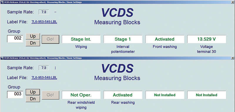
One obvious controller is Steering Electronics Address 16.
At measured value 002 field 3, the front washer status is either Not Oper. or Activated.
In this case, the display is “Activated” but the pump is not operating.
At measured value 003 field 2, the rear washer status is either Not Oper. or Activated.
In this case, the display is “Activated” but the pump is not operating.
The next obvious controller is Central Electrics Address 09.
At measured value 005 field 1, front washing switch is either Not Oper. or Activated.
In this case, the display is “Activated” but the pump is not operating.
At measured value 005 field 2, rear washing switch is either Not Oper. or Activated.
In this case, the display is “Activated” but the pump is not operating.
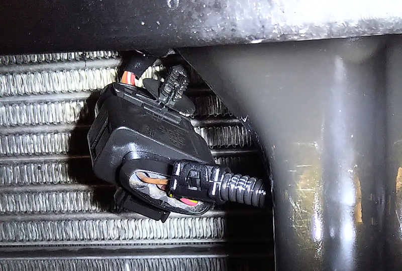
One thing to mention is the front wiper operation. With the hood open, the front wipers are NOT supposed to operate. The wipers did operate and the hood latch wiring was found to be disconnected (accident victim). The green connections were properly cleaned and sealed and the hood switch operated with the correct status at the following Address 09 Central Electrics:
- Measured value 006 field 1, front hood switch status conditions are: “Open or Closed but a Closed Hood = OPEN.” This is normal.
- Measured value 006 field 2, front hood switch status conditions are: “Open or Closed but a Closed Hood = Closed.” This is normal.
With an open or closed hood, the values switch within the respected fields.
This repair was completed, and continued to more testing.
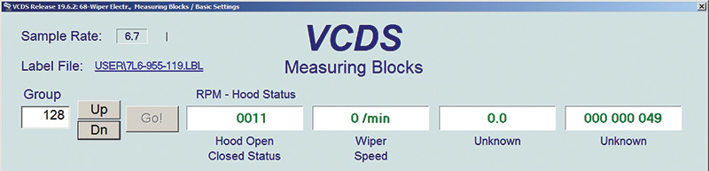
Another controller that monitors the Hood Open or Closed status is Wiper Electronics Address 68 and includes Wiper rpm.
Measured value 128 field 1, switch status conditions are: Hood Open or Closed
Status is 1011 = Open and 0011 = Closed
Measured value 128 field 2, switch status conditions are: Wiper Speed
Status is 0 = Off, 39 = Position 1 or Mist and 60 = Position 3
How is this even possible?! The two controllers display “activate” the pumps via network status but there is no washer pump activity. The output test passed as mentioned. As if!
Anomalies and odd values – look deeper
The technician discovered some oddities after an attempt to operate the washer pumps within the two controllers mentioned: Address 05 and 09.
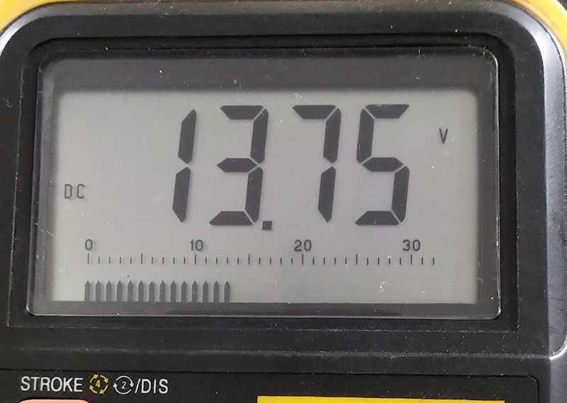
At Address 05, the voltage within the display fields didn’t match the volt meter readings at the “jump start” posts.
What about controller Start and Authorization Address 05?
This is now very interesting at Address 05 Group 055, field 1.
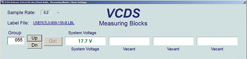
How is that even possible and what will Address 09 display?
This is an anomaly that indicates a voltage reading far higher with a power supply attached to the “starter or battery jump” posts and volt meter attached in parallel with the power supply.
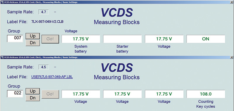
Pay attention to the Label File and text under each field. The text will change over time as testing, editing, and diagnostics progress into the evening.
17.75 V at two controllers? As if!
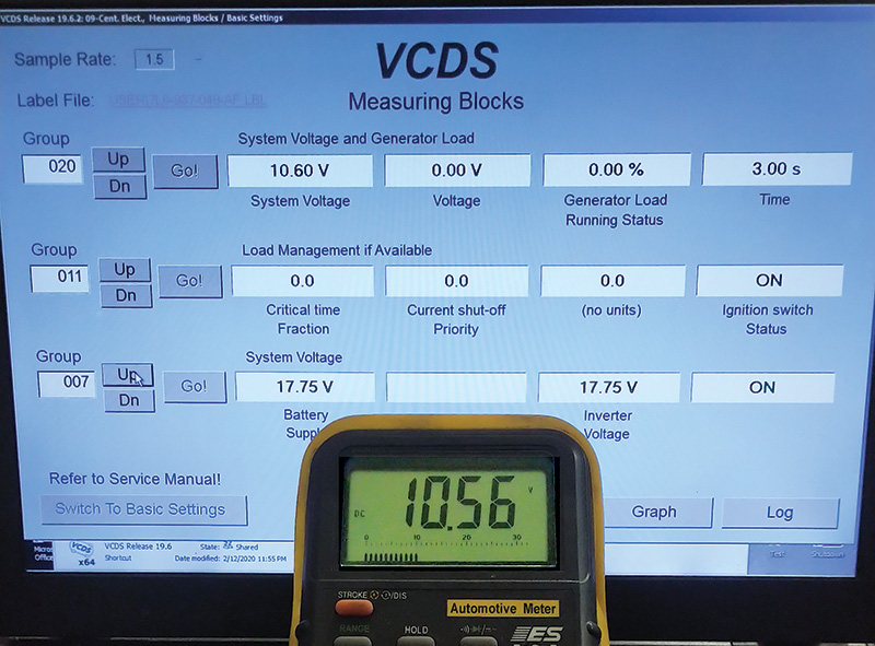
The first test was recorded at measured values 020, 011, and 007 at Address 09 Central Electrics. The test was about monitoring any intervention with Energy Management.
With this test, the key, lights, heater, heated seats, interior lighting, and radio all remained ON while the
volt meter was in view with the noted values.
The test began with a fully charged battery, while drinking lots of coffee and waiting until a dramatic crash occurred.
This test failed dramatically.
The anomalies remained and the diagnosis appeared to be a defective Central Electrics Controller. The voltage created is NOT possible with the fields when matched to the multimeter. The VW dealer mentioned a back order for a replacement controller for more than three weeks but searched for a used and identical matching part number. There was a belief that something was misleading during these tests. Writing, testing, and editing the Label Files were a great deal of help because there needed to be proof between what the scan tool was displaying and the values that were in view with the changes in status.
The technician photographed and saved the images through all of these phases. There was one particular photo of interest and it was decided to “go back to the scene of the crime.”
There were so many questions.
Who replaced the battery and where did it come from?
With the seat lifted out of place, how did they even get the battery out?
How was the battery cover damaged?
How were the seat rail covers damaged?
Why was there water on the floor?
Why were the front rail bolts covered in rust?
We understood from the body shop that they had tilted up the seat with the rear lower frame pushed up as well. That must have been something to see as they mangled the battery out from under the seat. As if!
The water on the floor
Touaregs are well known to have wiring issues under the carpet near the driver’s left foot.
That was promptly addressed and the floor was dried. The repaired harness was covered and secured. The retest offered nothing new.
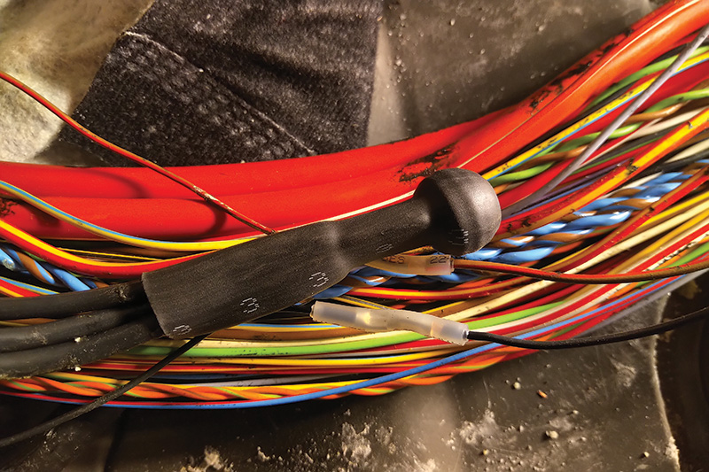
Capping the shrink tube and correct crimp/shrink splices
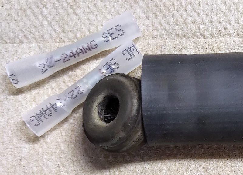
Crimp/shrink splices have been used for quite some time and are the perfect connection compared to solder. Normally the yellow, blue, and pink are used. Much smaller gauge harness repairs are performed with clear/white 22 – 24 AWG crimp/shrink splices. The technician capped the large shrink tube with a brake bleeder cap.
Fortunately for photos and recordings
One can imagine each test, each photo, and the length of time writing, editing, and saving any description that offered a hint as to why 17.75 volts was displayed between two controllers.
Identification is critical but so is sanity.
Part two of the adventure continues next month. Be sure to visit AutomotiveTechInfo.com/derfix to find out what happens next.
Download PDF


0 Comments