

| All diagnostic and repair examples in this article apply to the 2015-2018 Nissan Murano and 2016-2018 Maxima. Refer to your Nissan repair manual for repair procedure details about the specific Nissan model you are repairing. |
Problems with remote keyless entry, door handle request switch, push-button ignition switch, and remote engine start can each be symptoms of intelligent key configuration and signal transmission faults. Nissan symptom tables set you on the most efficient diagnostic path.
Intelligent Key system overview
The intelligent key (I-Key) contributes to the operation of the Nissan Vehicle Immobilizer System (NVIS), the vehicle security system, and the engine start system. Key components include an in-dash push-button ignition switch, intelligent keys that enable remote engine start and door lock or unlock, antennas that detect when I-Keys are within range and report their status to the BCM, lock and unlock request switches in the exterior door handles, plus additional support components.
An I-Key that is registered for that vehicle sends a signal that authorizes the Body Control Module (BCM) to lock and unlock doors. The I-Key signal also enables the push-button ignition switch on the dash to transmit an ON/OFF signal to the BCM to start or stop the engine.
Remote Keyless Entry (RKE) functionality allows secure remote engine start and remote door unlocking. A remote keyless entry receiver receives the signal from the I-Key button and enables transmission to the BCM.
An identification check by the BCM confirms whether the I-Key used is registered for that vehicle. Once the I-Key registration is verified, the BCM enables door lock function, ignition switch operation, and engine start.
The BCM also performs ID verification between itself and the Engine Control Module (ECM) before each engine start. Nissan BCM hardware is robust and failure is infrequent. Should repair require BCM replacement, the new BCM must be initialized so it and the ECM recognize each other. The installation procedure requires that you save the identification information from the prior BCM to use in setting up its replacement. Saving this identification information is best done before removing the original BCM from the vehicle. Refer to the repair manual for the specific Nissan model and year for procedural details.
Common fault causes
You can easily diagnose many intelligent key problems by understanding a few basic I-Key system operating requirements. These include having the key configured in the body control module, ensuring that the specific key is registered to the vehicle, and maintaining the ability for signals to transmit back and forth between the key and BCM.
Diagnostic Procedure
First, go to the Intelligent Key Symptom Tables in either the Door & Lock (DLK) or the Security Control System (SEC) sections of the repair manual for the model and year vehicle you are repairing. Match the symptoms from the vehicle to a description in the table. The symptom description will list the repair manual section and the page number where information applicable to the symptoms is located. In the Electronic Service Manual (ESM) version. A link next to each set of symptoms will connect to the appropriate diagnostic procedure information.
Intelligent key configured in the BCM?
The intelligent key is programmed to start the vehicle when it is either next to the push-button ignition switch, in the vehicle within the detection area of the inside antenna, or exterior to the car but near enough to be in the range of the outside antenna. If the vehicle will not start with the I-Key next to the ignition switch, near the driver’s seat or the exterior of the car, the intelligent key mode in the BCM may not have been initialized. Make sure before starting your diagnosis that the “ENGINE START BY I-KEY†setting in the “Work Support†mode of the “INTELLIGENT KEY†setup in the body control module is ON. This is the equivalent of checking that the toaster is plugged in if you notice that your bread is not being toasted.
Symptom Table 1 (both intelligent keys have the same symptoms) | |||||
| No. | Door lock operation (remote keyless entry) | Door lock operation (request switch) or back door open operation (opener switch of back door panel) | Engine started with push-button ignition switch operation (registered Intelligent Key is within the detection area of inside key antenna) | Engine started with push-button ignition switch operation (registered Intelligent Key placed next to push-button ignition switch) | Symptom |
| 1 | OK | OK | No start | No start | SEC-132 |
| 2 | OK | NG | OK | OK | DLK-258 |
| 3 | OK | NG | No crank, No start | OK | DLK-260 |
| 4 | NG | NG | No crank, No start | OK | DLK-262 |
| 5 | NG | NG | No start | No start | DLK-263 |
| 6 | OK | OK | No crank, No start | OK | SEC-133 |
| 7 | NG | OK | OK | OK | DLK-265 |
| 8 | NG | NG | OK | OK | DLK-266 |
| 9 | Poor Range | OK | OK | OK | DLK-267 |
Symptom Table 2 (One intelligent key has the symptom, other keys operate normally) | |||||
| No | Door lock operation (remote keyless entry) | Door lock operation (request switch) or back door open operation (opener switch of back door panel) | Engine started with push-button ignition switch operation (Intelligent Key is within the detection area of inside key antenna) | Engine started with push-button ignition switch operation (registered Intelligent Key placed next to push button ignition switch) | Symptom |
| 1 | NG | OK | OK | OK | DLK-269 |
| 2 | NG | OK | No crank, No start | OK | DLK-270 |
| 3 | NG | NG | No crank, No start | No crank, No start | DLK-272 |
| 4 | OK | OK | No crank, No start | No crank, No start | SEC-135 |
| 5 | OK | NG | No crank, No start | OK | SEC-136 |
| 6 | Poor range | OK | OK | OK | DLK-274 |
Key registered to this vehicle?
An intelligent key that is not working could be due to a weak I-Key battery, internal corrosion or other I-Key circuitry problem, or a faulty antenna.
When an engine start or door lock or unlock action is requested through a button on the I-Key, exterior door handle, or the in-dash ignition switch, a request signal is sent simultaneously to the intelligent key and the BCM. An electronic ID verification process uses two-way communication between the intelligent key and the BCM. The outside or inside key antenna handles the detection of I-Keys that are within range and registered to the vehicle.
The intelligent key system on the 2015 to 2018 Murano uses six antennas. Inside key antennas are mounted in the instrument center, the console, and the luggage area. Outside key antennas are located one each in the driver and passenger side exterior door handles, and a third in the rear bumper.
If no outside or inside key antenna detects an intelligent key that is registered to that vehicle, the BCM does not enable actuation of the requested engine start or door lock or unlock.
Lock and unlock switches on the driver or passenger side doors also allow control of locks from inside the vehicle. Request signals from these door-mounted switches transmit through the CAN system, not the inside antenna.
Signal transmission and antenna functionality
The BCM sets DTC B2621 (inside key antenna – instrument center location) when it receives an excessively high or low voltage from the inside antenna. The fault could be caused by either an open or short in the inside key antenna circuit, or a failing inside key antenna. The diagnostic procedure includes checking the inside key antenna input signal, looking for continuity between the BCM harness connector and the inside key antenna or ground, and testing the functioning of the antenna itself.
There are similar diagnostic instructions for DTC B2622 (inside key antenna – console) and B2623 (inside key antenna – luggage room), as well as for the three outside key antennas: DTC B2626 (outside key antenna – RH), DTC B2627 (outside key antenna – LH), and DTC B2628 (outside key antenna – rear bumper). All of the relevant repair procedures are spelled out in the Door & Lock (DLK) section of the 2015 to 2018 Murano service manual.
Check the signal between the BCM harness connector and ground using an oscilloscope. Connect oscilloscope leads to BCM connector M80 using terminal 123 or 124, and ground. The repair manual procedure for diagnosing DTC B2621 (excessive voltage from the inside key antenna) on the 2015 to 2018 Murano shows the acceptable signal range with the I-Key in one of two different locations; in or out of the antenna detection area. If the signal is within the specified range, the antenna is OK.
If the signal falls out of the designated range, check continuity in the circuit between the BCM harness connector and the inside key antenna. With connections at the BCM (connector M80, terminal 123 or 124) and the inside key antenna from the instrument center (connector M14, terminal 1 or 2) there should be continuity. With connections between the BCM harness and ground, you should see no continuity. If either result is not good, repair or replace the BCM harness.
If the BCM harness connector is OK, replace the inside key antenna (instrument center) and recheck for a good signal
between the BCM harness connector and ground using an oscilloscope.
Below are a few examples of intelligent key symptoms that demonstrate I-Key configuration, registration, and signal transmission problem diagnosis and repair.
| The engine does not start when the push-button ignition switch is pressed, nor when I-Key is inside the vehicle. Both keys exhibit the same symptom. |
Symptom details: Door locks operate normally with remote keyless entry or with the request switch on the outside door handle, but the engine will not start with the I-Key near the ignition switch or anywhere inside the vehicle.
This is an example of how when the I-Key has not been initialized in the BCM one or more key fob functions do not work. Check that the “ENGINE START BY I-KEY†setting in “Work Support†mode of the “INTELLIGENT KEY†setup in the Body Control Module (BCM) is ON.
If both I-Keys are configured in the BCM, check for trouble codes. Select “Self-Diagnostic Result†mode in CONSULT-III Plus to find any DTCs that have been set. Follow the troubleshooting procedure recommendations for each DTC found.
| The engine does not start when Intelligent Key is inside of the vehicle but does when I-Key is placed next to the ignition switch. This symptom can apply to one or both keys. |
Symptom details: The door lock opens and closes upon commands from I-Key 1 or I-Key 2, and the vehicle starts when either intelligent key is placed next to the push-button ignition switch, but not elsewhere inside the vehicle.
This example can involve either the I-Key not being configured in the BCM or a fault in signal transmission. First check for DTCs and work through the troubleshooting procedure for any that have been stored. Then using CONSULT-III Plus, make sure that the “ENGINE START BY I-KEY†setting in “WORK SUPPORT†is ON.
Once any trouble codes are resolved and you’ve confirmed that the I-Keys are configured in the BCM, review the symptoms again. The outside key antenna is working, as confirmed by the fact that the door lock operates correctly using the intelligent key. The intelligent key also works when pressed against the ignition switch. The only time it does not work is when inside the vehicle but not touching the ignition switch. This combination of symptoms suggests the need for a function check of the inside key antenna.
Use Nissan’s SIGNAL TECH II to check whether each inside key antenna can pick up signal transmission back and forth between the I-Key and BCM. The user guide will walk you through the inspection method. Refer to the Nissan Electronic Service Manual (ESM) or printed (pdf) version for replacement procedures applicable to any faulty inside key antenna you find. If there is no antenna failure and the problem is still not resolved, either the BCM needs replacing or there is an intermittent fault that requires further detective work.
| Door lock or unlock does not work using the Request Switch, all doors |
Symptom details: The remote keyless entry locks or unlocks the doors, and the engine starts remotely or with the I-Key next to the push-button ignition switch. However, the Request Switch on the door handle (any door) fails to operate.
This problem could be attributable to any of the three different possible faults described at the beginning of this article. These include the I-Key not being set up in the BCM, not registered to this vehicle, or not transmitting a signal to or from the BCM. Other causes could also apply.
First, go to the “WORK SUPPORT†mode of “INTELLIGENT KEY†in the BCM and make sure that the “LOCK/UNLOCK BY I-KEY†setting is ON. Then confirm that an I-Key that is registered to that vehicle is within the detection area of the outside key antenna.
Next, check for DTCs and perform the indicated trouble diagnosis for any detected DTC.
Problem not resolved? Use Nissan SIGNAL TECH II to check the outside key antenna. The antenna should be able to establish two-way communication between the I-Key and the BCM and verify to the BCM that the I-Key is registered to that vehicle. Once the I-Key is confirmed as belonging to the vehicle, the BCM accepts the lock or unlock request from the door switch. If the outside key antenna status is OK but the door locks are still not responding, use SIGNAL TECH II to confirm that the I-Key is sending a lock or unlock signal.
If the I-Key is sending a signal, and the outside key antenna is confirming the I-Key registration, check the door request switches. With the I-Key within 20 inches of the door lock request switch, operate the switch. In WORK SUPPORT mode of the CONSULT-III Plus intelligent key BCM diagnosis, the monitor should show the request switch status (REQ SW -DR for LH door, REQ SW -AS for RH door) change from OFF to ON and back. The request count (RKE OPE COUN1) for that door should also change by the number of times you press the door lock request switch.
Should the door request switch status not change as the request switch is pressed, check for voltage between the malfunctioning switch’s harness connector and ground. Refer to the wiring diagram to find front door connector D15 (LH door) or D115 (RH door). Turn the ignition OFF. Check the voltage between terminal 3 and ground. You should see battery voltage.
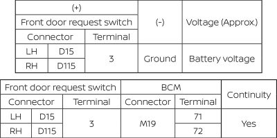
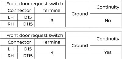
When the door request switch does not work even though it is receiving an input signal (voltage), check the door request switch ground circuit. There should be continuity between the door request switch harness connector (D15) tested at terminal 4, and ground. If you find no continuity, the front outside door handle assembly is malfunctioning.
If there is no continuity, check how continuity changes as you operate the door request switch. Turn the ignition OFF. Disconnect the malfunctioning front door request switch connector. Press and release the door request switch while checking for continuity between switch terminals 3 and 4. You should see continuity when the switch is pressed and none when it is released. If these conditions do not apply, replace the malfunctioning front door request switch.
Did you not find battery voltage between the door request switch’s harness connector and ground? Check for continuity between the request switch harness connector and the BCM harness connector. Use BCM connector M19, terminal 71 (LH door) or 72 (RH door). Then test to confirm there is no continuity between the request switch harness connector and ground.
If there is continuity between the request switch harness connector (D15, Terminal 3) and the BCM harness connector, and no continuity between the request switch and ground, you likely have a faulty BCM. If there is continuity between the request switch harness connector and ground, repair or replace the request switch harness.
You can test individual door lock actuators using CONSULT-III Plus. Failure of an individual lock actuator is not indicated in this case because the problem is occurring with all doors. Assuming that the I-Key is sending a signal, the outside key antenna is receiving it, and the door request switches work, either the BCM is failing or an intermittent error is occurring.
| All doors do not lock/unlock using the Intelligent Key button. Only one key has the symptom. |
Symptom details: The door lock does not work with RKE, but does with the request switch in the outside door handle. Engine start works with the I-Key within the detection area of the inside key antenna as well as with the key placed next to the push-button ignition switch.
Here is another example of key symptoms caused by either signal strength or key registration problems. Use Nissan’s Signal Tech II tool (J-50190) to check the intelligent key’s relative signal strength. Refer to the Signal Tech II User Guide for details. If the I-Key does not meet the minimum signal strength requirement, replace the key.
If the intelligent key meets the minimum signal strength specified in the Signal Tech II User Guide but does not work, re-register the I-Key and try again to lock or unlock the door using the I-Key. If the I-Key does not work after re-registering, replace the intelligent key. Register the new I-Key and check each of its buttons to make sure they work. It is unlikely that the new key fails, but if it does not work you may have a faulty BCM.
Intelligent Key battery
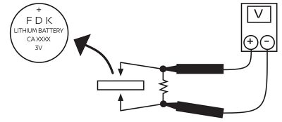
You can also use CONSULT-III Plus to check whether a weak I-Key signal is related to a battery problem. In the BCM section of the CONSULT-III Plus diagnostic menu, select “Intelligent Key.†In “Data Monitor†mode, select “RKE OPE COUN1.†Press various buttons on the I-Key one at a time. If the numerical value changes in the CONSULT-III Plus screen as you operate the I-Key, the key can send a signal.
If the count does not change, check the I-Key battery. Connect the battery to a resistance source of approximately 300 ohms so that the current value approaches 10 mA. If you see 2.5 to 3.0 volts on your DVOM, the battery is OK and you need to replace the intelligent key. Less voltage indicates a need to replace the battery.
Save diagnostic time
A variety of intelligent key problems can be caused by a key not being configured in the BCM, not registered to the vehicle, or not sending a signal. In addition to providing symptom tables, the Nissan service manual suggests the order in which you should tackle any DTCs. Refer to the service manual to streamline your diagnostic and repair time.
Nissan Anti-Theft System (NATS) antenna
Failure to communicate between the Nissan Anti-Theft System (NATS) antenna and the BCM results in the vehicle becoming immobilized. The BCM sets a B2198 DTC. The cause could be a faulty BCM, a failing NATS antenna, or a harness or connector problem resulting in an open or shorted antenna circuit.
There are two tests to confirm that the DTC is still applicable before beginning diagnostic work. DTC test 1: Touch the I-Key to the push-button ignition switch. Check for a DTC using the “Self Diagnostic Result†mode of CONSULT-III Plus.
DTC test 2: If your first test with the I-Key touching the ignition switch finds no DTC, conduct a second DTC search with the I-Key inside the vehicle but not touching the ignition switch. Press the push-button ignition switch. Select the “Self Diagnostic Result†mode of BCM and check for a DTC.
NATS diagnosis
The diagnostic procedure for DTC B2198 begins with disconnecting the BCM and NATS antenna amp and inspecting for disconnected, loose, or damaged connectors and terminals. Repair or replace connectors or terminals as necessary.
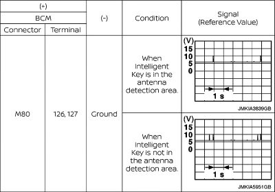
If there are no damaged connectors or terminals, check continuity between the BCM harness connector and NATS antenna harness connector. There should be continuity between the BCM harness connector M80 at terminal 126 and the NATS antenna amp connector M218 at terminal 3. You should also see continuity between the BCM harness connector M80 at terminal 127 and the NATS antenna amp at terminal 1.
There should not be continuity between the BCM harness connector, either terminal 126 or 127, and ground. If either continuity test results in a failure, repair or replace the failed harness.
If the harnesses pass visual inspection and continuity tests, use an oscilloscope to check for a signal between the BCM harness connector and ground. A good signal should have an approximately 5 volt baseline and briefly spike to 10 volts on a 5 second interval.
Finding a good signal suggests the BCM is faulty and replacement is in order. An out-of-specification signal indicates it is time to replace the NATS antenna amp.


0 Comments