

Piezo injectors aren’t just for diesels. Understanding new technology is the key to successful repairs.
When we discuss BMW fuel injectors we will focus primarily on the direct injection type or GDI. Port injection has been phased out and you will mostly see the direct type injectors in the field. Direct injection is not all that new.
BMW used direct injection in airplane engines in the 1930s. However they did not implement DI in automotive applications until the mid 2000s. In 2007 BMW introduced the N54 engine featuring direct injection and turbocharging on the 335i model.
BMW’s current lineup features almost all turbocharged and direct injected engines. BMW made the switch to direct injection for good reason — namely, improved fuel efficiency, lower emissions, better performance, and cooler cylinder temperatures. Are they bullet proof? Of course not. Yes Virginia, there is a recall. But before we get into that, let’s delve into what makes the modern BMW injector work.
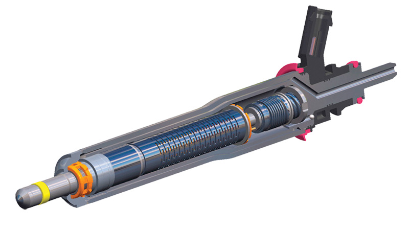
Modern BMW piezo injectors
Although manufacturers such as Bosch, Siemens, and Delphi are all working on a solenoid based injector design that will perform as well as the piezo type, we will focus on the latter as these injectors are what you will encounter most often.
According to Bosch, which introduced piezo injectors to the industry, a piezo actuator acts up to five times faster than a standard injector solenoid and the motion is frictionless. This translates into precise fuel metering and allows for multiple injector events to occur each combustion cycle.
A piezo element only expands a miniscule amount, so hundreds of slices are stacked on top of each other so that the net movement is only about 0.004 inch. The actual movement is microscopic, but enough to make the piezo element act as the valve.
Since this movement is a downward motion, a lever and spring setup inside the injector allows the pintle to open and close. In a piezo injector, the electronic engine management system sends an electrical signal to the valve, much like the solenoid operated valve. But the unique property of a piezo crystal, as mentioned before, is that it changes shape when exposed to electric current.
First high pressure fuel enters the injector; all the pressure throughout the injector is equal at this point. The piezo stack is energized by the fuel control unit and the injection event takes place. Piezo injectors are quieter and more precise than solenoid units, a huge benefit when microseconds count!
Some basics of piezo or high voltage injectors:
- The drivers in the DME control both voltage and current.
- The driver will provide a boost voltage of up to 200 volts.
- The driver will boost current to around 10 amps for a few hundred microseconds.
- Voltage returns to approximately 13.5 V and the holding current drops to around 3 to 4 amps for the remainder of the injection event.
Fuel system monitoring
We won’t spend much time on the theory and operation of the GDI system and how it works other than a bit of a refresher in regard to how the monitoring system affects the injectors. Previous articles have looked in depth at the GDI system as a whole. The self-diagnosis system as it pertains to fuel system monitoring, and particularly fuel injectors, can be broken down into:
- Lambda adaptation
- Trim control plausibility monitoring
- Diagnosis of injector aging
- High pressure fuel control system
Diagnosis of injector aging is simply a way of monitoring injector adaptation. A small proportion of the short term fuel deviation is used for diagnostic injector aging and is stored as an injector adaptation value in a separate map. The values of the separate map are renewed every 497 miles. A fault will be stored if the injector adaptation exceeds a calibratable minimum or maximum value.
In the monitoring of the high pressure fuel control system you will be dealing with codes such as p3282, p3284, p3003, and p3090. The high pressure system consists of a common fuel rail for all high pressure piezo injection valves, a fuel rail pressure sensor, a high pressure fuel pump with a built in fuel volume control valve, and an overpressure valve.
Based on the engine load and speed, the high pressure needs to be adjusted to pressures set forth in the map. To accomplish this the pressure in the rail is measured and controlled with the help of the fuel volume control valve. Using the desired fuel mass and pressure preset value, a precontrol calculates the driver signal as inputs for the fuel volume control valve.
In diagnosis, the high pressure monitoring system analyzes the difference between the measured fuel pressure and the set point pressure. Your scan tool often has PIDs that display requested fuel pressure and actual pressure. The monitor determines whether or not the set point value of the fuel rail pressure can be adjusted by the high pressure control.
If the rail pressure is too high, the result in the difference in the two values is negative. If the pressure is too low, then the difference in the two values will result in a positive. If either of these two values, negative or positive, exceeds a calibrated threshold for a certain amount of time, a malfunction will be detected with a fault set. The high pressure sensor signal is also monitored for plausibility by using the lambda controller.
If the adaptation shows rich while the fuel pressure controller is below a calibrated threshold, then a too high pressure signal will be detected. The reverse will occur when a lean condition is detected and the fuel pressure controller is above a calibrated threshold. This will result in a too low pressure signal.
Diagnosis
BMW models with turbocharged N54 engines and MSD80 DME software can develop fuel injector MOSFET driver failure. MOSFET stands for Metal–Oxide–Semiconductor Field-Effect Transistor. It is a field-effect transistor where the voltage determines the conductivity of the device. It is used for switching or amplifying signals, in this case switching the injector.
The ability to change conductivity with the amount of applied voltage can be used for amplifying or switching electronic signals. This driver failure will cause an injector to stop delivering fuel and an engine misfire to occur. The Check Engine light will be ON with these related fault codes (error messages):
- 30BA DME digital motor electronics, internal failure
- 30BB DME digital motor electronics, internal failure
- Here are some of the affected models:
- 2007-2013 BMW 135i (E82)
- 2007-2008 BMW 335i (E90)
- 2007-2008 BMW 335xi (E91)
- 2007-2010 BMW 335i (E92)
- 2007-2010 BMW 335i (E93)
- 2009-2010 BMW 535i & 535xi (E60)
- 2009-2016 BMW Z4 35i (E89)
BMW models with MSD80 DME software may set the fault codes 30BA or 30BB. These fault codes set when fuel injectors on bank 1 or bank 2 develop circuit faults or when an injector MOSFET driver fails. Most times these fault codes will be permanent and will not clear. However, be mindful there are situations where the fault codes will set intermittently.
When diagnosing piezo fuel injector fault codes it is a good idea to begin by checking fuel injector voltage and current using a lab scope. This will aid in determining whether the fault code is caused by the injector itself, the circuit, or the driver.
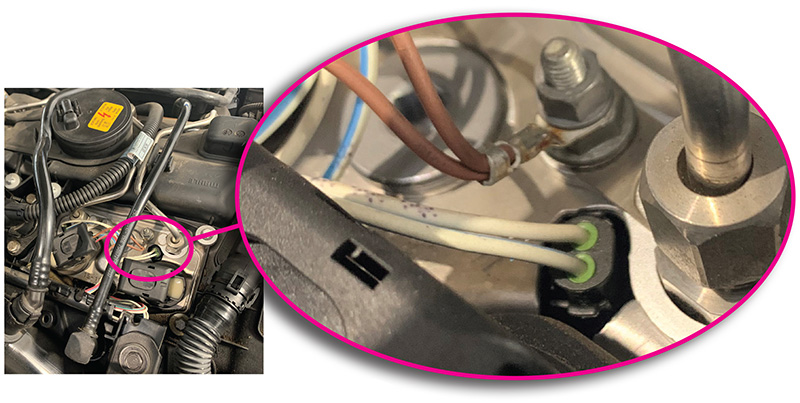
Remember, piezo injectors normally operate at extremely high voltages, so use extreme care when working around connections. Do not touch any of the injector terminals while the engine is running. Set your scope to display voltage and current at the same time. Set the voltage range to -200 volts DC to +200 volts DC. Current range should be set around 10 amps. Beginning on a cylinder with no faults, establish a possible known good pattern. Insert a back probe into the white wire, then attach your current probe around the same wire. Be sure to consult the wiring diagram for the specific model you are working on.
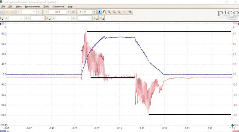
Voltage should range from 0 to almost 160 volts DC. The current pattern will peak at around 8 amps when the injector is switched on, then the current will drop while the injector is open, and, finally reverse when the injector is switched off. Current reverses because the piezo element acts as a capacitor, and when switched off, the voltage travels back through the injector. If the pattern isn’t right you most likely have a faulty injector or driver. Most times when the DME is at fault, the current pattern will try to climb, but fail. The MOSFET drivers fail when the attempt to charge the injector begins.
In the event you feel as though you have a faulty injector or driver, turn off the engine, remove your test equipment and disconnect all the injectors. Connect your scan tool, either ISTA-D or a factory compatible scan tool, and try to clear the codes. If the codes will not clear you most likely have a DME fault or wiring issue. If the fault clears then most likely the injector is faulty. Double check this as these babies are expensive!
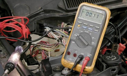
In checking your wiring integrity you will want to perform a voltage drop test of the wiring under load. This is a bit tricky in that, due to the high voltages the engine management applies, you can’t energize the circuit just by powering it up. You will have to supply your own load. First disconnect the negative battery terminal, then locate the DME and disconnect both DME connectors. Consult an accurate wiring diagram and use your ohmmeter to verify that you are on the correct wire from the DME to the injector.
Now that you have identified the correct wire, connect the injector side of the wiring harness to battery negative. Then, at the DME side, connect a test light (the load) to the injector terminal to be tested, then connect it to battery positive. You can use the jump start terminal if you wish, and the test light should illuminate. Use your voltmeter now and check the voltage at the DME connection and you should have 0.2 V or less. Check the integrity of all your suspect circuits including both legs of each injector.
If the fault code does not clear even when disconnecting all the injectors, and if the injector wiring tests OK, the issue has been isolated to the DME. There is a method for opening the DME and checking the MOSFET; however there are no serviceable parts internally so a new unit from BMW is the answer.
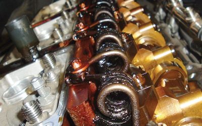
We have covered a possible electrical failure of the injectors and drivers, but what about a mechanical failure? A common symptom of a mechanical failure is a misfire coupled with: black smoke from the tailpipe; rich smelling exhaust; engine oil dilution; and even engine hydro lock. You may have misfire codes and rich fuel trims alerting you to the problem. What typically happens is the injector doesn’t completely shut and drips excess fuel into the cylinders. This is why it is imperative to not let these symptoms continue in your customer’s vehicle, and to repair the condition as soon as possible.
Recalls and warranties
BMW has issued a recall on certain models. This emissions recall involves E60, E61, E71, E82, E88, E90, E92, and E93 vehicles with N54 engines which were produced from 04/02/2007 through 11/30/2008. The piezo injectors may cause misfire faults with erratic engine operation.
Your customer may be entitled to repair from the BMW dealer. To check for recalls go to: bmwusa.com/safety-and-emission-recalls.html
Also, BMW has issued extended warranties on injectors for certain models according to TIS bulletin SI B01 05 18. N63T ENGINE FUEL INJECTORS: LIMITED WARRANTY EXTENSION TO 10 YEARS/120,000 MILES. TIS bulletin SI B01 02 15 has also extended the warranty on N54 Engine Fuel Injectors – Limited Warranty Extension to 10 Years/120,000 Miles.
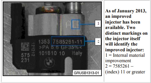
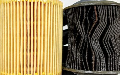
New injectors have been released from BMW for the N63, N74, and N54 with “improved internal filtering†and “special thermo compensating oil.†Unfortunately the new injectors have calibration and construction differences that prevent them from being intermixed with older style injectors “index 10,†but they can be intermixed with newer “index 11†injectors. So in some cases of injector failure, BMW owners might have to replace ALL fuel injectors depending on which injectors are already installed on their BMW.
What do all those numbers mean?
Here is a typical FI part number: 13537585261-12. The following is how the part number will read on the actual fuel injector. Here is the breakdown: BMW Part Number -13537585261 Fuel Injector Index: 12. BMW only manufactures injectors with an index of 11 or higher. There are two points to remember:
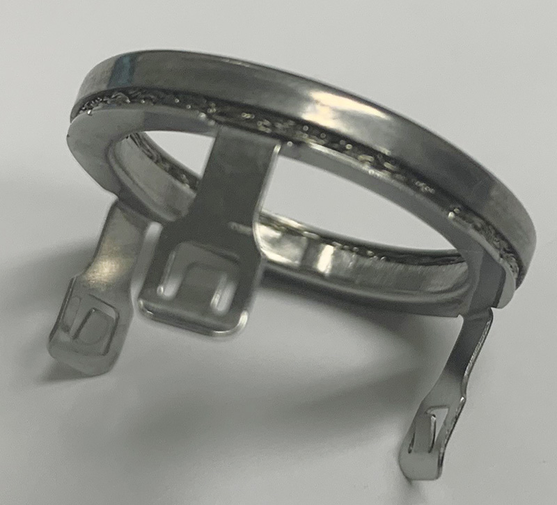
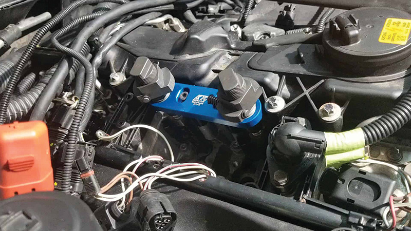
- Direct injection fuel injectors must use a new decoupling ring (13537564751) and a new seal (13537584315) when removed or replaced. These part numbers may vary depending on the fuel injector part number. New injectors will come with a seal installed, otherwise you will need a special tool to expand the seal when installing and compress it again.
- Fuel injectors with an index of 10 or lower cannot be paired with injectors that have an index of 11 or higher. They are calibrated differently and the newer injectors (index 11 and up) are made as a replacement for the faulty/defective injectors (index 10 and lower). This means that if the customer is replacing some injectors, but not all, you must check the index on the remaining injectors and to see if any of them have an index of less than 11. If so, those injectors will have to be replaced at the same time to prevent driveability issues and possible catastrophic engine damage.
In the end, all of the fuel injectors on a particular engine must have an index of 11 or higher. Most shops agree you should go with all new injectors index 12 and not have any issues in the future.
Calibration
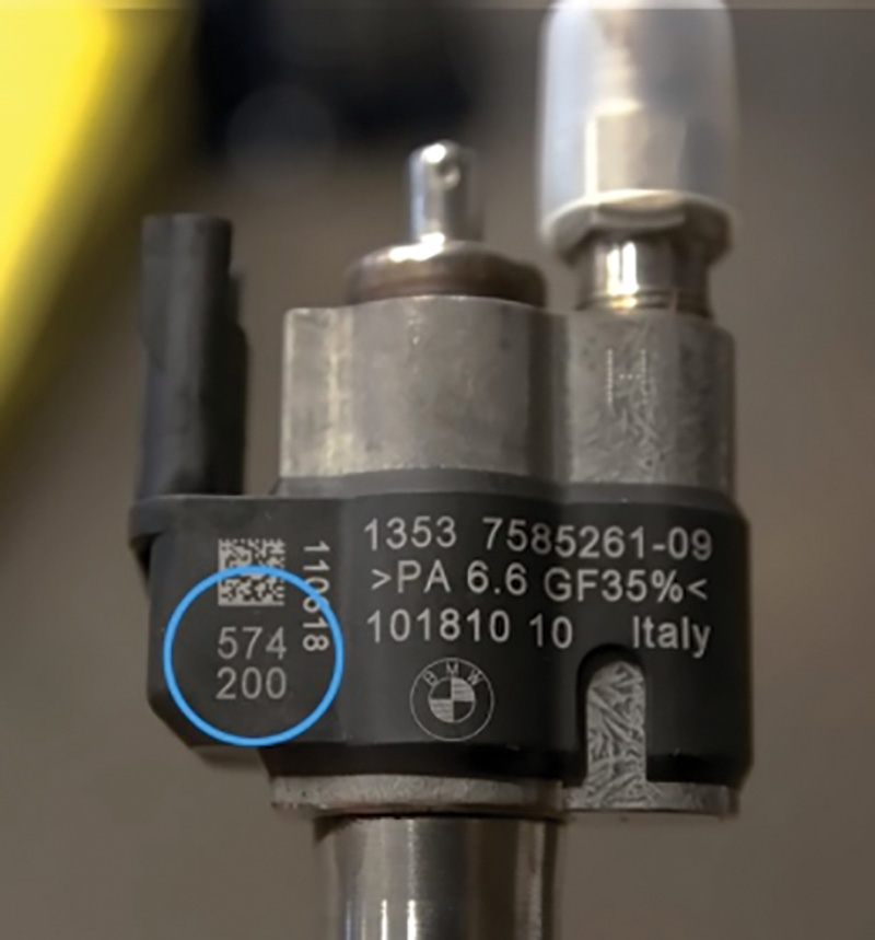
During vehicle assembly, after installation of the DME control module, the calibration values of each installed injector are stored in the DME control module. The calibration values are allocated to the individual cylinders according to the installation of the injectors. The injection volumes calculated by the DME control module are corrected by these calibration values, thus improving the exhaust emissions. Using ISTA-P or compatible scan tool these values can be changed or new values entered. The calibration values are printed in two blocks each with three digits on each injector. The inscription can be located either on the plastic bracket or on the metallic upper part. If injectors are renewed or replaced, it must be assured that the printed calibration values of each injector are assigned to the correct cylinder in the DME.
The menu on your scan tool will read something like this:
- Vehicle identification
- Function selection
- Select “Service functionsâ€
- Select “Engine electronicsâ€
- Select “Adjustment functionsâ€
- Select “Adjust injectorsâ€
- Injection quantity compensation
For each replaced injector, the adjustment value must be entered according to the installation location.
As these vehicles get more mileage on them, you are bound to see more fuel injector failures. Providing accurate diagnosis coupled with the latest parts updates will ensure your customers of a quality repair and peace of mind.

Thank you from a BMW enthusiast/upcoming BMW electrical specialist 🙂
Hello everybody.
Thanks BMW team.