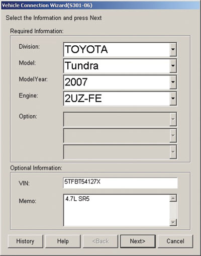
Vehicle under test and final repair: 2007 Toyota Tundra 4.7L SR5 Customer complaint: MIL lamp on
Toyota Secondary Air systems are complicated systems that work in accordance within the engine management systems and adhere to modern emissions standards. This article offers solutions/tests that aid in the diagnosis and confirm that the engine management system is accepting/complying with all messages/commands from Techstream.
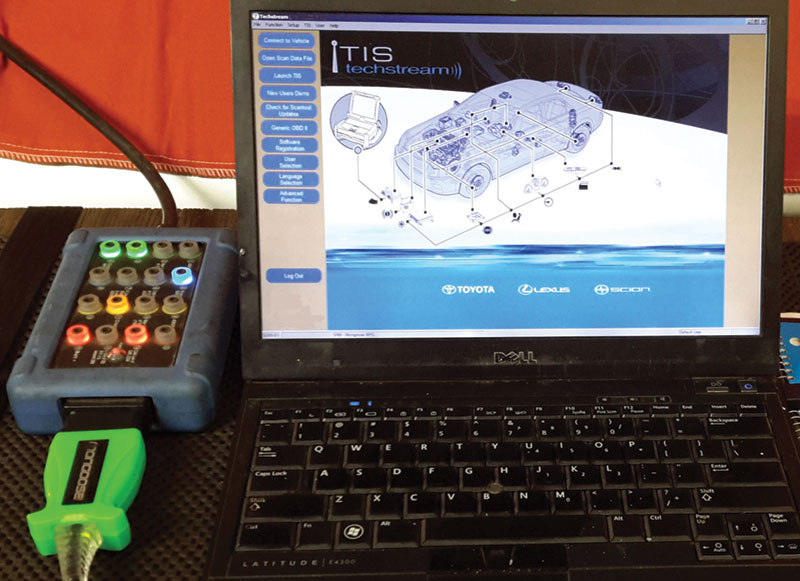
When the complaint is solved, Techstream will confirm the repair, ordering the readiness monitors set during final testing. Techstream messages are easily in view using a DLC breakout box attached between the DLC, the Mongoose Pro programming cable, and Laptop/Techstream combination. If there are any communication errors during diagnosis, the DLC breakout box can help determine the nature of that error using a multi-meter and oscilloscope.
NOTE: Regard this Toyota model as a modern and complex network of controllers that will affect their behavior dependent on recorded faults. Never program with a DLC box connected, direct connection only.
Procedures and tools used:
- DLC breakout box
- Drew Technologies Mongoose Pro
- Windows 7 operating system on a Dell
- Sony Camera
- Wiring schematic – model specific and TSBs – model specific
- Multi-meter and or oscilloscope
Note that this vehicle has high mileage due to its model year and occasional use off-road because of the nature of the customer’s employment.
Step 1) Perform an initial interview to gather the customer’s concerns as to “who, what, where and when.†Customer information is all-important to help in the concerns and time line. The environment and use of this vehicle are equally important. The task is “Condition, Cause and Correction.â€
Step 2) Using a clean/stable power supply attached to the battery and with Techstream, perform a complete vehicle scan (KOEO) noting the condition of the vehicle. Save the initial scan either by images or printouts and delete all recorded faults.
Step 3a) Depending on the recorded faults, perform a driving test to attempt to duplicate the customer’s concerns. Scan the vehicle again and save any and all recorded faults. Be attentive to any changes between scans.
Step 3b) In this specific case, the secondary air system has multiple faults and many of these conditions can be duplicated in the repair facility using Techstream and measuring tools such as a multi-meter or oscilloscope.
Step 3c) Inform the service representative of the required diagnostic steps and assure that the customer realizes the time involved to perform the correct diagnostic procedures and final tests. Make sure the initial images and prints are available for the discussion. Gather all relevant TSBs for this year, make and model along with service records if any are available. In this case, no records existed.
The TSBs are a very good guide for tests and torque specifications.
Using a Drewtech Mongoose Pro cable and Techstream, start with the identification and health of the vehicle, noting the faults that are based on the customer’s concerns with any other faults that are not known. If the Drewtech CarDaq Plus, CarDaq Plus 2 or CarDaq-M are available, they will both perform exceptionally well.
The initial faults will not indicate the full story, and additional tests may need to be performed to find the root cause of the faults displayed and recorded. Note the original faults. Techstream has very good functions built in to test the entire secondary air system, down to the individual component level. With additional tools, schematics and equipment, the emissions devices can be tested using the Techstream functions. The “Utility†tab can be used as a “bi-directional†control to test the secondary air emissions devices.
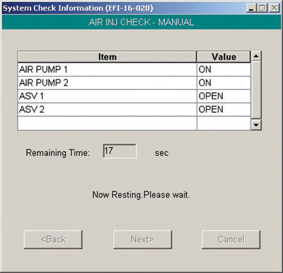
That function is chosen as a manual test for both air pumps and air switching valves with the engine running. Ensure attachment to an exhaust extraction system.
In this case, new faults are recorded and, additionally, this test added the possibility that one air pump and/or relay is defective. To repeat the test, the ignition key should be cycled after the wait period has lapsed (30 seconds) and faults deleted.
There are multiple methods to test if the switching valves have opened. One is to measure the upstream O2 sensor for a reaction when the valve(s) and pump(s) are operating individually, with an oscilloscope. Another is a “first look†sensor at the tailpipe. The O2 sensor will react with extra oxygen with an oscilloscope, or the “first look†sensor will quickly react to air pump pressure and pulses within the exhaust. Each active test will last 5 seconds.
During the active tests within Techstream, the tests will measure the current draw of each component, including pressure sensors, and if the tests pass during an emissions cycle, the oxygen flow will also be measured by the O2 sensors. In this case, both banks can be measured individually.
Techstream will drive the individual air pumps and generally be heard while the air pumps spin. With an amp clamp (using a meter or oscilloscope), measure the current and time that Techstream has each air pump activated. Techstream will activate the air pump(s) and open the air solenoids for 5 seconds.
The second test for the air pump(s) is relatively simple. The control module to drive the air pumps is accessible and air pumps can be enabled with battery power to “spool up†the air pumps. Any air pump activity can again be heard and a noisy/inoperative air pump can be easily diagnosed with KOEO. Note any unusual noises and the location of a suspect air pump.
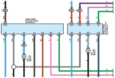
HINT: Battery power also means that the fuses (50 A) can be measured and used as “battery power†(both DA3). With the schematic, apply B+ to each pump (E10 blue wire and D67 white with blue wire). View the next image.
Follow the provided schematic (portion) but print a matching version.
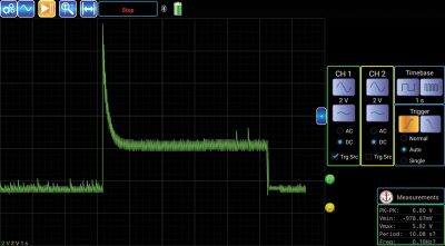
With Techstream, a schematic, an amp clamp with a meter or oscilloscope, a good and new pump will look similar to the next image. The spike is pump ON and the current draw is active for 5 seconds. The current drop is pump OFF. This test was completed using the Techstream option. Keep your notes and values on the matching schematic. Track the progress, tests and outputs as proof of concept and time spent on diagnosis.
With this waveform, measure the current draw and match both measurements at each air pump. The image is of a known new part. This simple test should also prove any replaced pump active within the system.
In this specific test on this specific vehicle, the air pump at the RF fender was extremely noisy and the air pump under the intake manifold had an open circuit. What could NOT be tested is the ground tab for the air pump under the intake. The wiring for the RF fender air pump can be tested but it did spool up.
The air switching valves can be tested with a multi-meter for open or short circuits (including shorts to the body of the valves). The control for the switching valves can also be tested using Techstream for commanded activity to each valve. The valves can be tested for binding in either direction by monitoring live data for the pressure sensors. If the valve is closed, the pressure sensor will not read any exhaust pulses and the opposite is true when the valve is open.
HINT: With the KOEO, verification for the air solenoid and control driver is to power each bank and listen for the solenoid’s perceptible noise.
For bank 1 – Power PIN B6 black with white wire.
For bank 2 – Power PIN B6 black with blue wire.
Also with Techstream, monitor those two inputs when the vehicle is running with the output test operating. No input = defective secondary air driver.
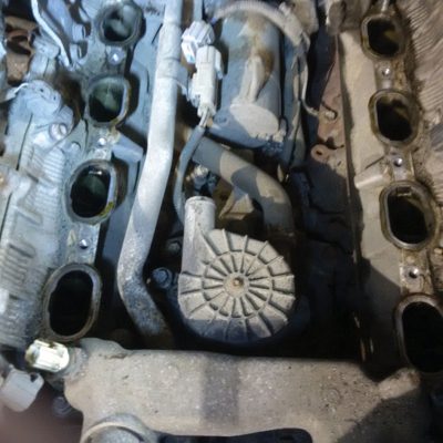
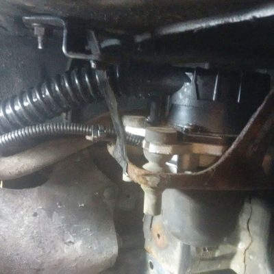
The Repair: This specific Toyota required both air pumps and both air switching valves to be replaced. Each pump has a different part number and they are not interchangeable. All gaskets and seals for the switching valves MUST be replaced. The intake manifold must be removed to access one pump (1), the inner RF fender liner requires removal to access the second pump (2).
Be aware if one or more pumps are suspect with internal damage; check for debris within the air valves. Check the metallic connections for other debris or oxidized material at all of the connections between the air pumps and air valves.
Additional to this specific repair was a suspected coolant leak as the coolant was about to be drained. At least 2 liters of fluid was added to test for the leak and nothing was found at ambient temperature after ¾ of an hour under pressure. Minimal cleaning and vacuuming was performed to remove most of the dirt and accumulated sand/salt to prevent intrusion.
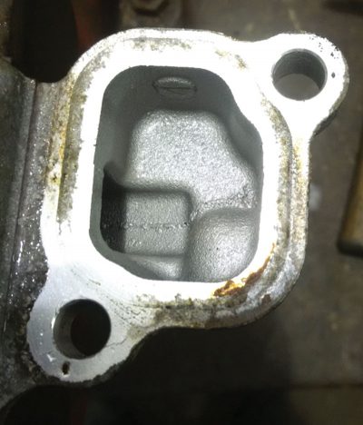
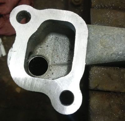
At the front and rear of this engine model there are two aluminum crossover manifolds for coolant transfer at both cylinder heads. Under the rear transfer manifold is where the leak was found between the cooling transfer manifold, gasket and passenger cylinder head.
Two images are included and indicate what happens when routine service is not performed in at recommended intervals. The used/old coolant attacks the aluminum, seals and gaskets over time.
The repair is simple, with a new/flat/clean quality file used to “draw file†the manifold and test each cleaned surface with a flat gauge. Measure and test any draw-filed surfaces in multiple directions. The concept is to only remove enough material to clean and flatten the surface for mating. All surfaces should be cleaned, polished, and tightened with the correct factory torque specifications during assembly.
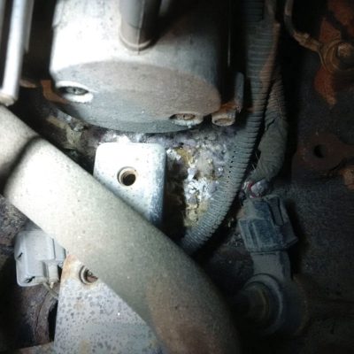
This repair also involved some rodent intrusion and the engine valley required cleaning and vacuuming. The harness also required a visual inspection but no damage was found and no wiring repairs were required.
HINT: Double check all disconnected harnesses for any dirt, liquid or damage during assembly. Clean the connections when required and replace any damaged locking connector shells.
Clean any and all rodent debris if evident; clean out the water drain beside the starter motor and also the air pump negative connection to the right of the starter motor. Now is the time to ensure the ground connection is in perfect condition. Check the starter B+ connection and condition before continuing with the intake manifold installation.
HINT: The new air pump can be tested before the intake is assembled. Testing is accomplished directly at the control module. The second motor can be tested in a similar fashion. Clean and assemble the intake manifold with new seals and ensure the tuning port is free.
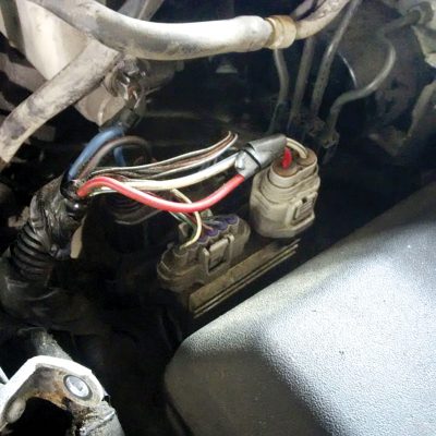
Note the connection of the air pump harness and ground connection bolted to the engine block.
Plug ALL open intake connections with shop towels before any cleaning is attempted.
HINT: In harsh environmental conditions where salt is the enemy, the salt and sand can bind/stick to the aluminum components. One very good cleaning method is using a carbide blade or small perfectly sharpened file ground at 15 degrees. Do not scratch, gall or damage the surfaces.
The final polish can be accomplished with an abrasive pad on a flat surface. This will ensure perfect sealing upon assembly of the cooling and intake air manifold. At times and in harsh conditions, some assembly bolts may be oxidized. Clean and visually pay attention to the thread surfaces. If in doubt, replace the affected bolts.
If the TSB was followed, an updated inlet tube was also connected to lessen the amount of dirt and water ingested at the RF fender location. Inspect that area for impacted dirt and wash that area with water. Make sure the inner fender liner is not damaged or any other body part is missing.
After following the service manual, using the correct procedures and replacing the coolant, Techstream can be used to verify the repair. In this specific case, all tests passed and no faults were set. The secondary air monitor also ran in the service bay.
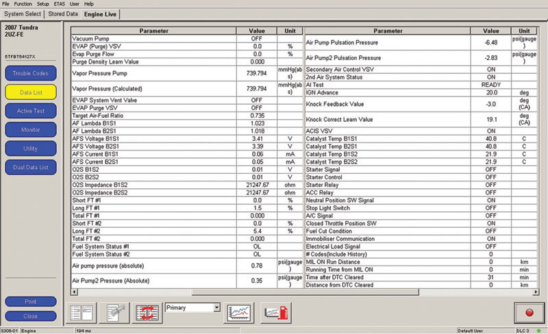
The best test after filling/bleeding the cooling system is to monitor the live data at a cold start. At a cold start, the secondary air system will activate quickly; therefore be ready with measuring equipment if further testing is required. Techstream’s live data screen will now indicate the correct operating parameters compared to the defective AIR system the customer arrived with. Pay attention to that screen but realize how that data is drawn on the screen.
NOTE: Each value is requested by Techstream and calculated/drawn into the correct placement. The next value is requested and again calculated/drawn into the correct placement. This process will be repeated throughout the entire screen until the first value is requested again, repeating the process. Therefore, average all of the values over time. The speed of Techstream will depend on the speed of the computer processor and interface used between the computer and vehicle. Also consider other applications running in the background. Close them for best results.
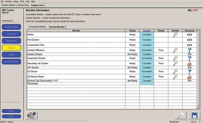
During the warm up phase and monitoring the live data, some of the readiness monitors may begin to activate in the service bay. Notice in the next image the monitors that set during warm up phase and up to normal running temperatures. Within these last images, the entire process may have taken approximately 30 to 45 minutes to clear the faults and come up to temperature with some monitors set. This model will require a final mixed and city road test to complete the monitors if this vehicle requires an emissions test.
Final: When the customer returned a few days later for a re-check, it was noted by the customer that “this Toyota has never run so well†after the repair.
Toyota vehicles will definitely run and behave extremely close to the factory settings after engine management faults are repaired when using factory parts and procedures. This model, along with many others, will exhibit poor performance when emissions do not meet federal, state, or local requirements. This is part of Toyota’s strategy when it comes to emissions, and is one positive approach to have the customer visit the repair facility for the required repair and/or updates.
Attentive owners will certainly appreciate the engine management system behavior when the faults are correctly repaired and the car is delivered to the customer in a timely fashion. “Do it right the first time†and the customer reaction will be positive towards the service department.
Remember: Gather the following TSBs and support program; T-SB-0160-11, T-SB-0029-08 and CSB-ZTQ. Find a suitable schematic.



0 Comments