
A study in Toyota’s pink coolant and some of the cooling system components that utilize this coolant including electric coolant pumps, EGR coolers and heat exchangers.
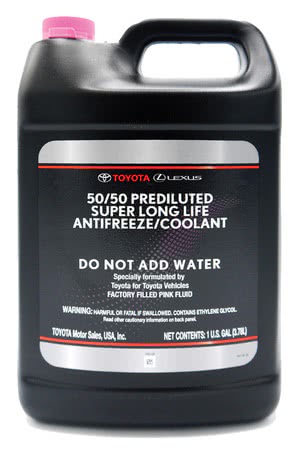
In 2004, Toyota transitioned from red Long-Life Coolant (LLC) to the improved pink Super Long-Life Coolant (SLLC). Pink SLLC is pre-mixed with deionized water for convenience and the assurance of a proper mix. As its name implies, SLLC lasts for a very long time. The first replacement interval is usually at 100,000 miles. Toyota currently recommends SLLC for all Toyota cooling systems, both for the internal combustion engine and hybrid power electronics.
In this edition of TOYOTAtech, we’ll take a look at Toyota’s pink coolant and some of the cooling system components that use this coolant, including electric coolant pumps, EGR coolers and heat exchangers.
What’s With All the Colors?
Originally, a coolant’s color was due to the chemicals and anti-corrosive agents that were used during formulation, but with modern coolants that no longer holds true. Today, most coolants are dyed a unique color.
Manufactures do this for several reasons. First, the different colors help to distinguish one type of coolant from another. Another reason for dye is that it makes it easier to see the coolant when checking the level in an overflow tank or inspecting for a coolant leak under the hood. Finally, the most important reason for the different colors is to make sure the correct fluid is being added to a vehicle, since mixing coolant types can lead to serious complications down the line.
Mixing coolant types or using the wrong coolant can have several negative consequences. These issues include a shortened life span of the coolant, increased corrosiveness and can lead to gelling of the coolant or even electrolysis issues. Coolant gelling can restrict a radiator or clog a heater core, and electrolysis can quickly damage aluminum components. Always use the recommended OE coolant type to avoid these issues.
Toyota red LLC is still available. If you use LLC or an equivalent for an older Toyota, take care when mixing. Use deionized or distilled water, and measure then confirm the ratio. Failure to mix coolant correctly will result in cooling system performance issues. The following is Toyota’s official statement from service information.
In order to avoid technical problems, only use “Toyota Super Long Life Coolant” or similar high quality ethylene glycol based non-silicate, non-amine, non-nitrite, and non-borate coolant with long-life hybrid organic acid technology. Follow the manufacturer’s dilution recommendations on the label.
An Age Old Question

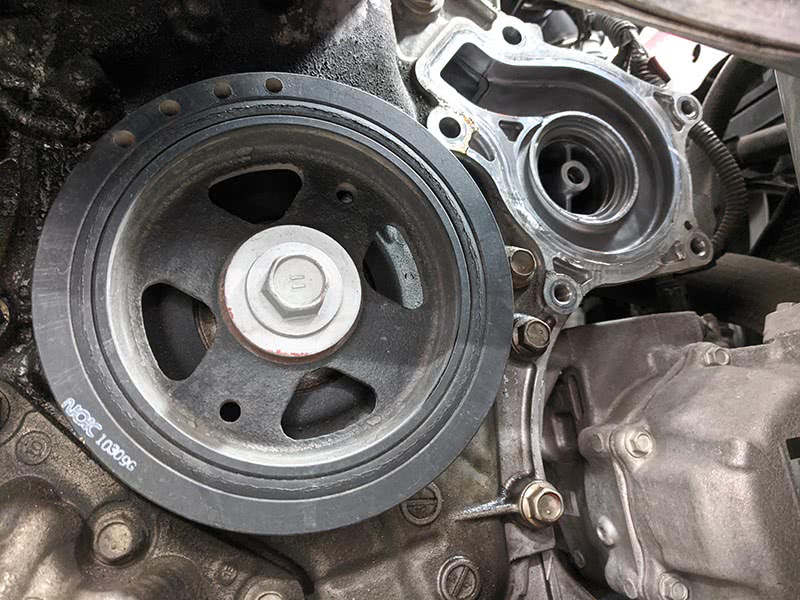
A second generation 2007 Toyota Tundra has been dropped off at the shop for a 5K service and inspection. While performing the service the technician notes dried coolant stains by the water pump pulley shown in the photo below.
The technician finished the inspection and submitted his findings to the service writer. The service writer made an estimate for the pump along with a few other minor service items. After a phone call to discuss recommendations and pricing, our customer asks a question we’ve all heard before – “Do I really have to replace it now, or can it wait for a while?” The book time on the water pump is just under five hours, so it’s not an inexpensive repair and our customer’s question is reasonable.
The question opens up an age-old debate: What constitutes a leak that must be repaired, and what is a seep that’s ok to monitor? It’s a gray area and can be subject to each technician’s opinion, but there’s a fine line we must walk. Being overzealous when recommending repairs can lead to damaged customer relations. On the other hand, if the engine overheats after leaving the shop, the customer will want to know why you said he could wait.
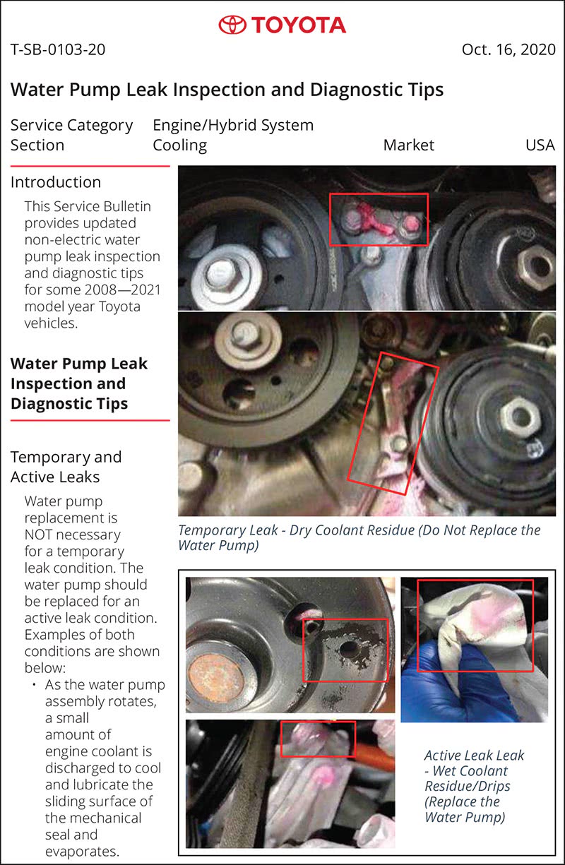
A shop should create a standard for all their technicians to follow in regard to fluid leaks, with definitions of each type of leak. For cooling systems that may include the following: dried coolant, seeping, active leak or dripping coolant. By communicating this grading system, along with detailed photos to a vehicle owner many potential issues can be avoided.
To help navigate these muddy waters, Toyota has released Technical Bulletin T-SB-103-20 which provides clear examples of seepage and leakage for non-electric water pumps. These examples can be used for other cooling system components as well.
One final thought on low coolant levels. Keep in mind that coolant does evaporate, so a decrease in the overflow tank level over time may not necessarily indicate a problem. In a typical cooling system, the mixture of coolant and water could be anywhere from 40—60% water and the portion that is water will be slowly evaporating. The rate of evaporation can vary due driving habits, climate, and other environmental factors, but a drop of an inch per year in the overflow can be normal. This may not sound like much, but it can add up over time if the coolant isn’t topped up with every service.
EGR Coolers
Traditionally found on diesel engines where combustion pressures and temperatures are at their highest, Exhaust Gas Recirculation (EGR) coolers have found their way onto gasoline engines. There are several Toyota engines that utilize an EGR cooler as part of the emissions (and cooling) system. An EGR cooler is an air to coolant heat exchanger that cools the recirculated exhaust gasses before they are re-introduced to the air intake.
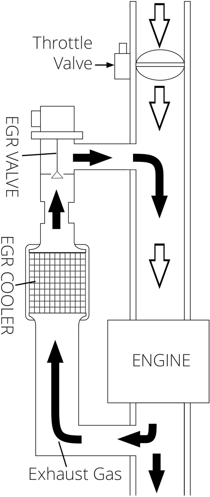
The main purpose of EGR systems is to lower in-cylinder temperatures and thereby lowering the production of Nitrogen Oxides (NOx) which are a negative byproduct of internal combustion. The EGR cooler aids in this process by further cooling the exhaust gasses before they are recirculated and improving the overall efficiency of the system. The cooler sits inline of the exhaust gas flow just before the EGR valve (see EGR System Diagram).
While the cooler is ultimately an emissions control device, it relies on coolant from the engine’s cooling system to function. The cooler sits high in the cooling system, so proper coolant level is important. This makes regularly checking the coolant level and properly bleeding the cooling system after repairs extremely important.
The cooler has been added as an emissions device to the under hood Vehicle Emission Control Information label, with the abbreviation EGRC, so if there is ever confusion to whether an engine is equipped with an EGR cooler consult the under hood label.

A potential issue with the EGR cooler is an internal coolant leak. Due to thermal cycling, the cooler might crack, resulting in a hard-to-find internal coolant leak. The coolant would leak into the EGR tube and then be burned off through the engine. Symptoms would include loss of coolant, white steam from the tail pipe, and eventually overheating once the coolant level was low enough.
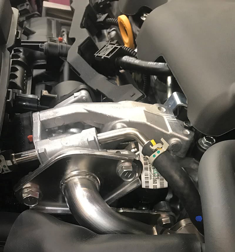
Exhaust Pipe Heat Exchanger
Another cooling system component found on the third and forth generation Prius is the exhaust pipe heat exchanger. The exhaust pipe heat exchanger is similar to an EGR cooler in that it is also an air to coolant heat exchanger, but it transfers heat in the opposite direction. Instead of coolant cooling the exhaust gasses, the heat from the exhaust is used to warm the coolant from the engine. The exchanger is part of the Exhaust Heat Recirculation System.
The heat exchanger is used on later model Prius Hybrids to heat the engine up faster for reduced emissions and improved heater operation after a cold start. The following excerpt from the ‘New Car Features’ of Toyota’s Technical Information System (TIS) explains the purpose and components of the exhaust heat recirculation system.
Exhaust Heat Recirculation System:
- The exhaust heat recirculation system (exhaust heat recovery unit) consists of a heat exchanger, exhaust gas control valve and exhaust gas control valve actuator.
- Engine coolant is circulated to the exhaust pipe in order to heat it. With this, the engine warm up time has been reduced and fuel economy is improved. Also, the time taken for the heater to become effective in winter is reduced.
- The exhaust gas control valve is opened or closed by a thermostat on the actuator. The exhaust gas control valve has a mechanism which automatically opens the valve when the engine coolant becomes hot.
There are coolant lines that run down to the exchanger, which sits directly behind the catalytic converter in the front exhaust pipe assembly. Due to the location of the heat exchanger, it is possible for coolant to leak into the exhaust pipe and be burned.
Toyota has released technical bulletin T-SB-0135-19 when dealing with a low coolant level and an illuminated MIL. According to the bulletin, the fault that would be stored is P148F00, which by definition is for the engine coolant pump over revolution. While at first glance this code seems unrelated to a heat exchanger issue, the code description is slightly misleading. A low coolant level is a common cause for the fault because low coolant can allow the electric water pump to spin faster than the engine controller expects.
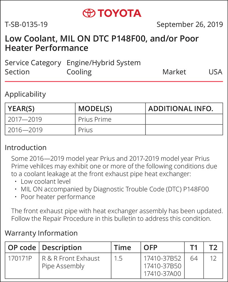
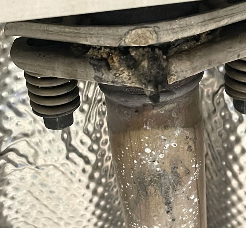
A leak in the heat exchanger will typically result in white smoke from the tailpipe and could be incorrectly diagnosed as a failed head gasket. If a heat exchanger leak is suspected the exhaust pipe should be examined for stains and the pipe may need to be disconnected to inspect inside. The TSB lists an updated front exhaust pipe assembly to address the failure point of the heat exchanger. This assembly is rather expensive, so care needs to be taken when diagnosing a faulty exchanger.
Electric Coolant Pump
The third generation Prius introduced several changes to the best-selling hybrid vehicle. One of these upgrades was the electric coolant pump. The water pump was the only component still being driven by a belt via the crankshaft pulley on the Gen2 Prius. This means the Gen3 Prius has no drive belt, and a somewhat odd-looking smooth harmonic balancer. Not only can the electric pump save energy by operating at the necessary speed, rather than always matching engine speed, but it also eliminates the need for a separate heater pump.
Let’s take a look at diagnosing and replacing an electric coolant pump on a 2011 Prius with a 1.8 liter 2ZR-FXE internal combustion engine. The vehicle was brought to the shop with a check engine light that came on after a long drive.
A scan of all modules on the vehicle found one fault in the ECM for the engine coolant pump – P148F “Engine Coolant Pump Over Revolution.” As previously mentioned this fault can simply be caused by a low coolant level, but that was not the case for this Prius. The coolant was right at the full mark on the expansion tank.
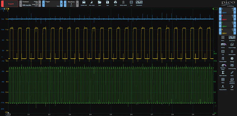
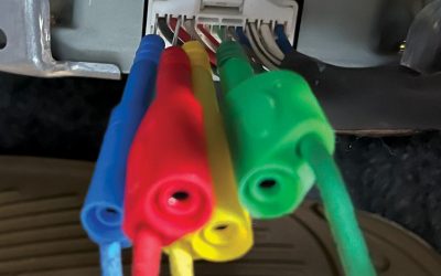
After reviewing the code set criteria and testing information, we connected a lab scope to the four wires at the coolant pump connector to capture waveforms while we were performing the Toyota’s test procedures for P148F.
Channel A in blue is connected across the power and ground wires to the pump. Channel C in green and channel D in yellow are the command and feedback signals to and from the coolant pump. Despite all signals looking OK, the water pump was rotating faster than the ECM was commanding, possibly due to the impeller slipping on the shaft.
This confirmed that the coolant pump was failing and needed to be replaced. The new pump was ordered from the local Toyota dealership and when it was delivered the installation began.
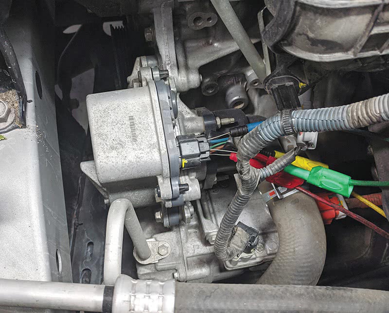
The location on the electric coolant pump and the replacement procedure are very similar to the previous belt drive pump. Make note that two of the five bolts are longer than the others and require a different tightening torque.
Once the new pump is installed, the engine needs to be put into Maintenance Mode to keep the internal combustion engine running and properly bleed the cooling system. This procedure is outlined in service information and if executed correctly will result in the multi-information display reading “Maintenance Mode.” After the coolant pump was replaced and the cooling system bled, an extended road test was carried out with no issues or faults present.
No matter the coolant’s color, a solid understanding of the cooling system components and following the correct testing and repair procedures will result in quality work and satisfied clients. Take a moment to check service information before starting any cooling system diagnosis or repair. Knowing what systems are present and how they function will save time in the long run and produce better results.
By Jordan Hill
Excellent resource…… thanks for making it available to me.