
It turns over, but won’t fire. Spark, fuel, or compression? Get the answer quickly.
So where to start with no starts? This scenario is often described as a Crank, No-Start. Well, the best start is with a good question and answer session with the customer, especially if the problem is intermittent. It may only occur when hot, after sitting in the grocery store parking lot. Maybe it is only first thing in the morning. The important thing is to get as many details about the customer’s concern as possible in order to correctly diagnose and solve the problem.
Your customer might not be able top describe the symptom accurately, so it is really important to listen carefully and ask careful questions to identify the complaint. Often a married couple will have two completely different descriptions of what’s going on and you have the makings of a great comedy scene. This is where good questioning and listening skills come into play as part of the diagnosis.
Strategy Based Diagnostics
We’ve touched on this concept before, but whenever discussing any diagnosis – and no-starts are no exception – we find it useful to have a brief refresher on the concepts. A good technician combines experience, system knowledge, observations and test data along with manufacturer literature to develop some theories and then prove or disprove each one.
Always start by verifying the complaint. Skipping this step will have you chasing your tail by trying to fix a problem different from what exists in the vehicle. Once confirmed, get out your most powerful diagnosis tool: your brain.
The basic idea is to identify every component that could possibly affect the system, and then look for which one(s) are not operating properly. Use the Mercedes-Benz STAR TekInfo or WIS wiring diagrams and system function descriptions if necessary. With a list in hand, check the easiest-to-check components first, and move on to the more difficult items if necessary. For example, a quick check of the fuel gauge reading could save a lot of time if the tank is empty.
Once your tests have identified a possible cause, you can start making repairs. If that doesn’t address the complaint, pick up where you left off, as it is not impossible to find two different causes for a particular complaint. Hopefully, in the end you have not only corrected the complaint, but you’ve given some thought to why that part failed in the first place, and taken actions to prevent it where possible.
In a crank, no-start situation, here is a basic list of components and systems that are involved. We will have a closer look at each of these:
- Battery
- Fuses
- Wiring
- Security/Anti-Theft
- Control Modules & Relays
- Fuel Supply
- Ignition Components
- Engine Compression
- Engine sensors
Spark, Fuel, or Compression?
With only these three things needed for an engine to run, it sounds like it would be easy to narrow it down, but as we all know the details get complicated. If all three happen at the right time, the engine will start. Being able to test for all of these is important, but modern engine control systems have a wealth of self-diagnostics that can really help point us in a direction. And don’t limit yourself to the engine module: Related systems can also cause problems. Of course, diesel engines only need fuel and compression, 33 percent easier!
Quick Test
After verifying the customer concern, (or maybe not, sometimes it starts right up!) a complete scan of the vehicle is in order. Using your XENTRY Diagnostics system or compatible scan tool, make a note of any codes stored in the various modules. Compare similar codes (i.e. voltage codes) and incorporate that into your diagnostic strategy. Remember when using any scan tool you need to supply robust power to the vehicle. Allowing low voltage during diagnostics can cause problems, which could have you chasing ghosts. Even worse is a power drop during programming, which can possibly cause module damage. Mercedes-Benz recommends a dedicated automotive power supply with protection circuitry, capable of more than 30 amps at battery voltage.
Battery
You may wonder why you need to check the battery – after all, it cranks, right? Yes, well, the real question is how low does the system voltage drop during the high load from the starter motor? A weak battery might allow system voltage to drop too far, but be barely noticeable when checking cranking speed by ear.
Mercedes-Benz batteries are generally either AGM (absorbed glass mat) or conventional (flooded) lead acid. Some newer models, including Hybrids, may have exotic Lithium-Ion batteries or even multiple batteries. Later models tend to have AGM almost exclusively, especially if they are found in the passenger compartment or trunk as opposed to under the hood. WARNING: Only specifically-trained personnel should service batteries rated above 12 volts. Some batteries have lethal voltages! This article doesn’t cover these specialty systems.
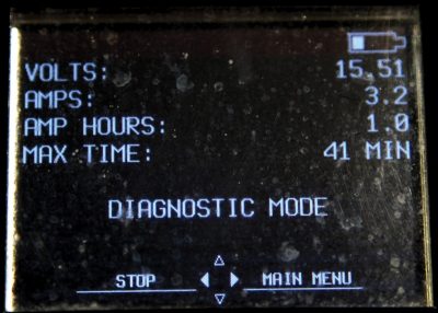
Dual-battery systems range from a tiny 1.2 Ah secondary battery (used to ensure the transmission can always be shifted into Park) to a relatively large (about 50 Ah) auxiliary battery used to run vehicle systems when the ECO Start-Stop system has switched off the engine. Use a high-quality battery tester to check all the batteries in the car, paying particular attention to the one that runs the starter. Mercedes-Benz recommends the Midtronics line of testers (see mbusassep.com for recommended equipment) but there are many high-quality testers on the market. Pick a reputable brand to be sure.
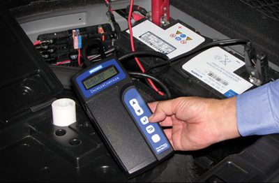
If the battery needs to be charged, it is a best practice to disconnect the battery from the vehicle. In two-battery systems, charge both batteries. When working on electrical systems, be sure that all batteries are disconnected by their ground terminal, otherwise a short-circuit hazard may exist. Accidentally shorting a wrench between a live power source and ground will definitely make for an exciting day, and not in a good way.
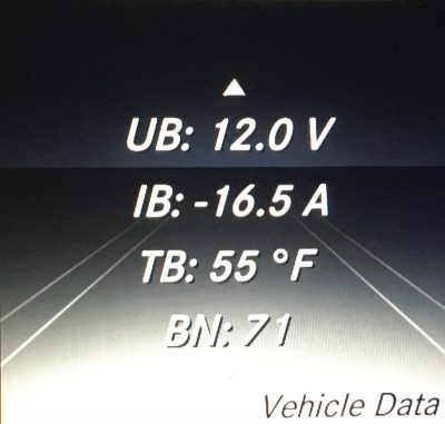
As a quick check, you can read the battery voltage using a voltmeter or, in many models, directly on the instrument cluster, as described in WIS document AR54.10-P-1132A. A battery should be charged if the measured voltage drops below 12.2 V. A good tester will tell you if the battery needs to be charged and retested. Some testers have a mode of diagnostic charge. This mode charges and tests the battery at the same time to give a very accurate analysis of its condition.
Check the Fuses!
This step is often overlooked, but remember to start with the basics. Before moving on to more complicated theories check the fuses – all the fuses – as there may be three or more fuse boxes, and fuse cards are often simplified as to what fuse protects what. It is frustrating to find your concern was a supposedly unrelated fuse. If using the XENTRY Diagnostics system the integrated test routines will often direct you to a specific fuse depending upon the complaint.
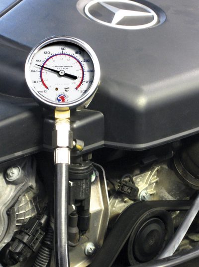
Fuel Pressure
Of course, you have verified the car has some fuel in it. But is enough fuel being delivered? A scenario: The 2010 C300 quick test turns up codes for possible faulty fuel pump or communication codes with fuel pump control unit. You can hear the pump running briefly when cycling the key. The fuel pump (M3) is actuated via the fuel pump control unit (N118), which in turn is controlled by the ME-SFI control unit. The pump draws fuel through an integrated strainer. Check the 20 amp fuse #42 at the rear SAM and 7.5 amp fuse #4 in the front SAM, testing both sides of each fuse for power. At the fuel pump control unit, verify Circuit 30 (constant battery power) on connector 1 Pin 1 (Red/Green wire) and Circuit 15 (key-on power) on connector 2 Pin 5 (Pink/White wire). Check for a good ground on connector 1 Pin 2 (Brown wire).
Be sure to use a voltage drop test when checking powers and grounds. Wires carrying current always have inherent resistance to current flow. Voltage drop is defined as the amount of voltage loss that occurs through all or part of a circuit due to that resistance. While a voltage drop at a component is expected – this is what powers the component – drops in the supply and ground lines can indicate a problem.
To check for voltage drop in a circuit, connect your voltmeter between the battery positive pole and the device’s power input (such as the fuel pump). Energize the circuit and read the voltage drop. Repeat between the battery ground and the component ground. Much higher than about 0.6 volts and your component could be suffering undervoltage, so you’ll need to trace the wiring to find the cause of the excessive voltage drop.
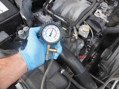
At normal output, the fuel pump in this model will deliver approximately 85-90 psi. Compare your gauge measurement with the sensor value shown by your scan tool. Low fuel pressure can indicate a clogged fuel filter or damaged fuel line, or possibly the fuel pump itself has worn and needs replacement. Be sure to check for damaged wires at the pump and correct or replace as needed.
Communication Errors
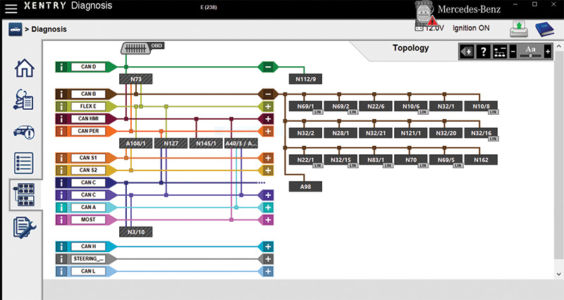
In some E-Class (211) models, communications error codes in the Central Gateway (CGW), or a control unit not responding to the quick test, can be an indication of a CAN Bus problem. If a system is not receiving the messages it needs because of a CAN fault, a no-start condition is possible. Locate the CAN Bus wiring for the Engine CAN (green & green/white) and Body CAN (brown & brown/red) on the Central Gateway Module (CGW). Using a voltmeter (or an oscilloscope if you have one) you can check the Bus voltages. Normal DC voltages (to ground) for Engine CAN are 2.6 volts (CAN-H) and 2.4 volts (CAN-L), and for body CAN are about 4.5 volts (H) and 0.65 volts (L), both with the ignition on.
CAN Bus testing is a process of elimination. If any voltage is incorrect, disconnect and reconnect connectors from the CAN Bus voltage distributors one at a time until the problem disappears – the disconnected branch is the problem. Good indicators of CAN Bus problems include a component failing to respond to a quick test, a “display defective†message on the instrument cluster, and several control units showing communications codes. CAN Bus voltage distributor locations are specified in STAR Finder and WIS.
Let’s take another example: A W204 C300 with the fault code “No Controller Area Network (CAN) message was received from control unit N118 fuel pump control module.†A test procedure in this instance might be to access the control unit (beneath the right rear seat) to test power and ground and CAN Bus voltages. If you have an oscilloscope, check the CAN Bus signal pattern for distortions. Issues with the CAN voltage distributor X30/21 have been found on this particular model: Remove the voltage distributor and inspect it for corrosion, possibly caused by clogged cowl or evaporator drains.
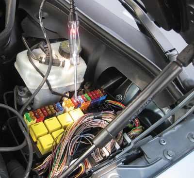
No Spark
Rarely will you get this symptom by itself, it will usually be accompanied by a no fuel pressure symptom as well. The exception would be in much older models where the fuel and spark management systems are separate. If you do need to do a pinpoint test to check for ignition spark, it is important to take some precautions to protect the control unit. According to Mercedes-Benz WIS document AH15-10-P-0002-01D you should never check spark by trying to jump the coil output terminal to ground. For field testing it is recommended to use a spark plug attached to a good engine ground and the coil boot to check for evidence of spark, while taking precautions against accidentally igniting anything. In coil-on-plug engines, use the inexpensive ignition testing adapter (See WIS or ask your Mercedes-Benz dealer) to check the ignition pattern.
The typical ME-SFI ignition system consists of:
- Knock sensors
- Mass Air Flow (MAF) sensor
- Camshaft position sensor(s)
- Coolant temperature sensor
- Accelerator pedal sensor
- Crankshaft position senor
- Throttle valve actuator
- ME-SFI engine control unit
- ETC (transmission) control unit
- Spark plugs and ignition coils
- A 16- or 38-pole Diagnostic connector
Sensors
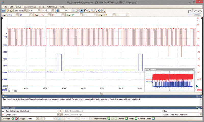
A generic code of P0336 or specific codes of 0117, 0119, and 0120 on a C230 (203 chassis) typically indicates a fault in the tooth count or wiring of the crank sensor. Observe your scan tool and monitor the engine RPM while cranking. If no RPM is detected, the crank sensor or wiring may be faulty. Check the three pins on the connector: Pin 1 is ground, Pin 2 is signal, and Pin 3 is the 5-volt reference. If Pins 1 and 3 are correct, reconnect the sensor and check Pin 2. The waveform from the crank sensor while cranking should be a 5 volt square wave.
If you are working on a Mercedes-Benz 203 chassis, the front and rear edges of the segmented teeth will produce an alternating voltage which will look like a pulsed sine wave. The higher the engine speed, the higher the voltage. The permanent magnet located in one segment of the flywheel causes a change in the signal which is used for detecting the respective ignition circuit. The failure of the crank sensor is keenly associated with intermittent no-starts: When the sensor gets hot, the sensor can open internally and fail to produce voltage. As it cools down, it starts working again. We’ve seen this issue in several models over the years. Keep in mind the type of sensor you’re monitoring, as not all have this type of pattern. Always good to consult the manufacturer’s specifications.
If indeed you do find a faulty sensor, a relearn is required on the new-style hall-effect sensors. If vehicle does not start, P0336 code may get re-flagged as a result, even if there is nothing wrong with the sensor. Look for a re-initialization icon on your scan tool on the control unit adaptations menu.
Sometimes you may have what seems like a flooded condition. You may smell fuel when cranking or are able to start the vehicle in clear-flood mode. Black smoke may be emitted upon start up. You might have pulled a spark plug for inspection and found the electrode to be all full of black soot. These are possible indications of a faulty engine coolant temperature sensor. Sometimes this will not set a code unless the sensor goes so far out of range that the processor deems it implausible. A sensor that tells the ME control unit that the temperature is -40 degrees will cause the injection of too much fuel, thereby causing the flooding problem.
Anti-theft Systems
As mentioned, if the immobilizer anti-theft system is not operating properly, the engine will crank but fail to start, or in some cases crank for just a brief moment. In newer models, the engine won’t crank at all if the immobilizer is active, sometimes not letting the key turn.
While complete diagnosis of a Drive Authorization System (DAS) concern is well beyond the scope of this article, reading the fault codes will bring you a long way towards identifying the cause. In general, if the DAS system doesn’t recognize the vehicle key as valid – bad key, bad transponder coil, mis-matched control unit, or some other fault – a DTC will be set. As always, your XENTRY Diagnostics machine will walk you through the test procedures, or you can check in the Diagnostic Manuals found on STAR TekInfo.
So there you have it: Using a structured approach to a crank, no-start complaint, during which you consider all of the possible components and systems, will lead you to a firm conclusion. While checking the easiest items first, don’t stop until you’ve found the root cause. Staying well-organized will keep you from getting confused or lost, instead your careful notes on tests performed and results observed can be used later to verify your findings.
Not every problem can be solved quickly, but there are only so many parts in a car, and eventually you will find the one that needs your attention. Use your expertise, collect data in a logical way, and consult the myriad resources that Mercedes-Benz offers to successfully remedy that no-start condition.


0 Comments