
We explain the design and function of these turbo systems as well as diagnosis and repair of turbo-related problems.
Almost every vehicle manufacturer has begun moving toward using forced induction engines. Turbocharged and supercharged engines utilize compressed air to increase engine fuel efficiency and power. With emissions restrictions getting tighter and tighter, vehicle manufacturers have to increase fuel efficiency and decrease emissions every model year. Generally, to lower tailpipe emissions, using a smaller displacement engine is the easiest way to achieve that goal. This is fine for an economy car, but larger, heavier full-size vehicles can struggle to maintain speed and acceleration with a small displacement engine.
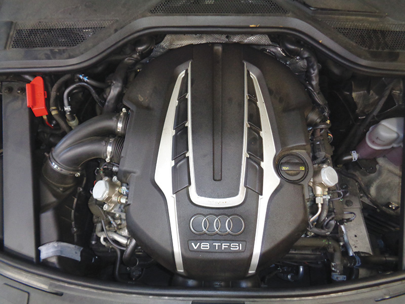
Audi has been utilizing forced induction powerplants for a long time and is no stranger to using them on many of their models. The 4.0 liter V-8 TFSI with dual twin scroll turbochargers is the focus of this article. This engine is available in multiple Audi and Bentley models. Audi A8, S8, S7 and even the Bentley Continental share this powerplant.
This engine is the first Audi V-8 to use twin turbocharging and is based on the previous generation 4.2 L V-8. Many modifications were made to the old design to increase power and fuel efficiency. Audi is always at the forefront of engine technology and its newest generation V-8 is teeming with technology and power.
By adding dual twin scroll turbochargers, base power for the V-8 engine is at more than 400 horsepower. Twin scroll turbos are more efficient at moving exhaust gases. This is accomplished by designing the exhaust manifolds in a way to reduce pumping losses for each cylinder, increasing overall efficiency and power. Each exhaust passage has its own direct path to the turbine to eliminate any pumping losses from an adjoining cylinder. This further increases power and torque, particularly at lower rpm.
As with every other modern forced induction engine, charge air cooling is necessary to lower boost temperature. Audi uses an air-to-water intercooler design on the 4.0T engine. By using a separate heat exchanger circuit with an electric coolant pump, charge air temperatures can be kept much more consistent than with an air-to-air cooler.
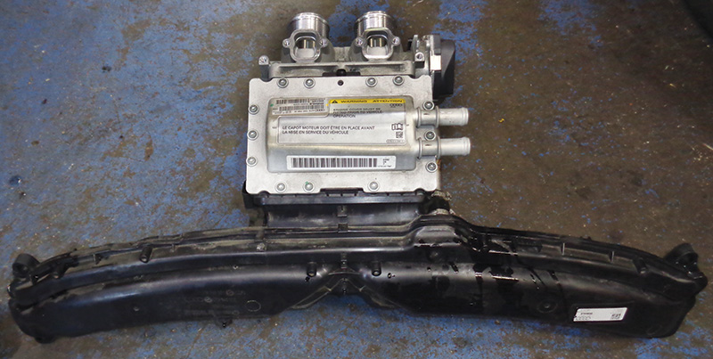
The air-to-water cooler utilizes a small coolant radiator at the front of the car to further lower intake temperatures. These are mounted very low at the front of the car, often sustaining damage from parking and other low speed maneuvers. Watch for coolant leaks here. Air-to-water coolers also reduce the length of the necessary intake runners, reducing perceived boost lag. The charge air cooler on the 4.0T engine is mounted directly on the top front of the engine and must be removed during turbo replacement.
To further increase fuel economy, Audi has also employed cylinder deactivation on this V-8 engine. This system selectively shuts down half of the engine, effectively making the vehicle run as a 4 cylinder when in operation. Cylinder deactivation is only useful in light/partial throttle driving when full engine power is not required. This system operates through Audi’s valve lift system. By using a camshaft with sliding lobes to engage different camshaft profiles, a solenoid for each lobe can quickly change cam profiles. This is a complicated system to save a few miles per gallon but has proven to work quite well with minimal issues.
Audi has designed this system to be as seamless as possible for the driver, attempting to reduce increased engine vibration from cylinder deactivation through the use of active engine mounts, and even using active noise cancelling through the stereo to minimize noise. Such luxury! As a side note, these engine mounts are fluid-filled and take considerable abuse. Internal valving controls fluid flow inside the mount to stiffen or soften the mount to lower engine oscillations and vibration. During vehicle service, always check the mounts for signs of fluid leakage, a clear sign of a failed engine mount. The engine mount fluid generally resembles dirty ATF, dark red in color. It’s smart to replace engine mounts in pairs when one has failed.
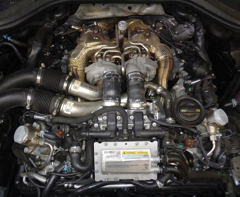
Audi, as well as many other vehicle manufacturers, has begun putting everything they can in the valley of the engine. Crankcase breathers, oil separators, oil coolers, intake changeover valves… the list goes on and on. This is partly due to packaging and size requirements for the vehicle.
On Audi vehicles, turbocharger placement in the valley is primarily done to ensure air induction flow efficiency. Intake air flow has a much more direct path without restriction when turbochargers are mounted in the valley of the engine. This increases power and efficiency by giving the engine unrestricted air flow. The catalytic converters can also be mounted closer to the turbochargers with this design. Having the catalyst closer to the turbochargers allows it to heat up to operating temperature much faster, further decreasing tailpipe emissions.
One major concern with mounting turbochargers in the valley of the engine is heat and temperature management. Turbochargers can get extremely hot during use, even more so during highway and spirited driving. This can become a problem when many engine components are made of lightweight materials that may not withstand the constant extreme heat cycling. Audi has done their best to design the engine to withstand such heat and also be able to dissipate excessive turbo heat when necessary.
It is important to take extra caution when working under the hood on these engines as many of the plastic breather lines, vacuum lines, and coolant lines can become brittle from heat exposure. Breathe on a higher mileage engine the wrong way, and plastic lines will break. If you have to remove PCV/oil separator hoses during service, it’s wise to recommend replacement. These can become particularly brittle as they are exposed to oil as well as heat.
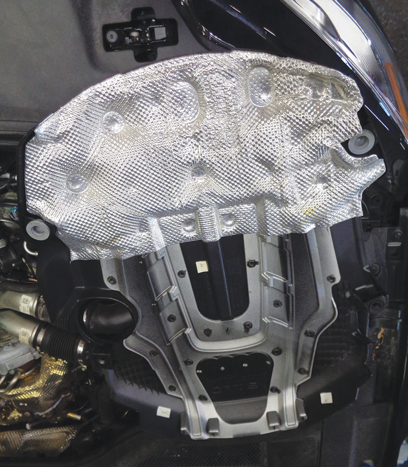
It is critical to never run the engine without proper engine covers. Shielding is installed on the lower half of the engine cover to divert heat away from the hood and bulkhead of the vehicle.
Audi also utilizes an under-hood temperature sensor mounted near the turbochargers in the valley. If excessive under-hood temperatures are found, this system activates the cooling fans to lower engine bay temperatures. The engine cover is used to divert under-hood air flow as well. Again, do not run the engine without covers properly installed!
The crankcase breather/oil separator module is mounted behind the charge air cooler in the valley on the 4.0T engine. This module handles all of the fine oil separation and ventilation for the engine. PCV valves lead a difficult life, particularly when directly under two turbochargers!
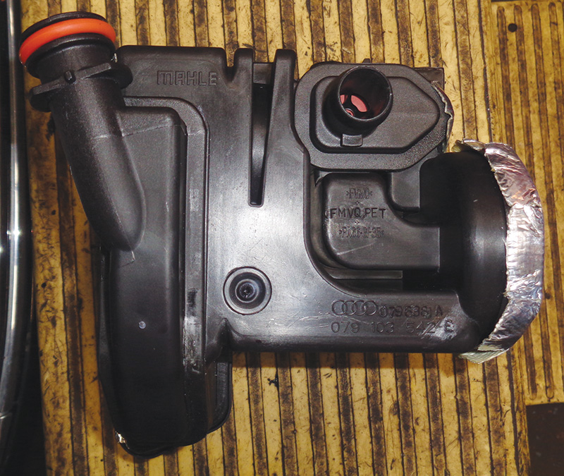
Oil separators are critical to deal with blow-by gases in the crankcase. By using a labyrinth style separator, oil droplets are efficiently removed from the gases and returned to the engine oil supply. Oil is returned to the crankcase via the oil module, which is mounted under the oil separator.
Pressure regulation is just as important for the separator to keep the engine properly sealed during operation. Pressure regulation still relies on a spring-loaded rubber diaphragm installed in the separator. These diaphragms are robust but are still known to fail periodically. Lean run faults and a whistling noise coming from the engine are your best hints that there is a failed pressure regulation valve. If suspecting a bad pressure regulator, a smoke test is also a great way to determine whether the diaphragm has failed. These valves have a visible weep hole on the diaphragm side and will show smoke through a smoke test if failed.
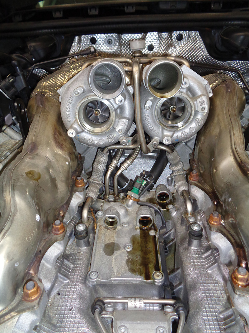
Because the engine turbochargers are mounted in the valley, oil supply and return must also be secured in the valley. Audi refers to this as the oil module. This module is mounted directly below the turbochargers in the center rear of the valley. In addition to oil supply and return for the turbos, the crankcase ventilation oil returns also pass through this module. Because they are located directly below two turbochargers, this module and engine oil can get quite hot. This extreme heat can be detrimental to the engine oil, causing coking and oil breakdown.
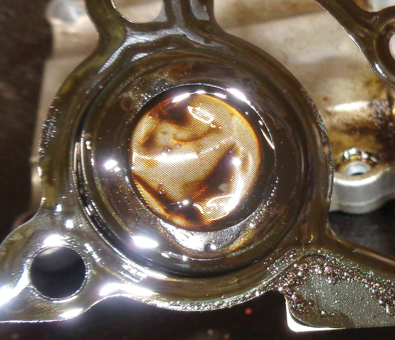
Audi has installed a screen in the oil module to protect the turbocharger oil supply from contaminating the oil. This oil supply screen can become blocked with sludge, effectively cutting off oil supply to one or both turbochargers. Oil supply blockage is the number one killer of turbochargers on this engine and is, unfortunately, not uncommon. This is why it is important to stress proper oil change intervals to customers. These engines do not do well with longer intervals between oil services. Oil contamination and blockage can also be traced back to poorly manufactured oil filter elements, which can shed material
into the oil supply system.
This oil supply blockage has become such a problem that aftermarket manufacturers are selling oil supply screen relocation kits. Unfortunately, due to the oil modules’ location, servicing the factory oil supply screen is almost impossible with the turbochargers installed. These aftermarket relocation kits make checking and cleaning the supply screen an easy task during oil service. But relocation kits are not factory approved.
Audi has released technical service bulletins for turbocharger failures on the 4.0T engine. These failures are happening even on lower-mileage vehicles between 40 and 80 K miles! Always check technical service bulletins as an initial diagnostic step. Following technical bulletins can eliminate the diagnostic dart board and quickly help you hone in on the real problem and fix for many vehicles.
If you have a customer’s vehicle with suspected turbocharger failure, a few steps are required to verify failure. Most common complaints for failed turbochargers are no start and hard start issues. Low power and engine stalling are also common complaints. Generally, the engine will not store faults directly relating to turbo failure. Lean bank one, bank two, and cylinder misfire faults are usually the only hints you may find by scanning for faults in the ECU.
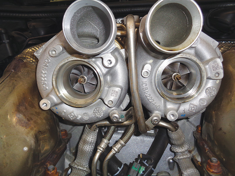
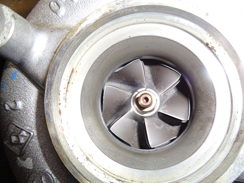
In many cases, oil blockage kills one turbocharger before the other. This can be more difficult to diagnose as the vehicle will probably run but be low on power. This is where visual examination of the turbine is necessary to determine failure. A borescope is an absolute necessity here to examine the turbochargers without disassembling half the engine. By removing the upper air inlet pipes toward the air box, the borescope may be inserted toward the turbocharger cold/inlet side turbine. Turbine damage is what you are looking for here.
If oil supply to the turbocharger journal bearing is obstructed, the turbine will quickly fail. Without lubrication, and if the turbine contacts the turbocharger housing, important clearances are destroyed, and the turbine will destroy itself in short order. Customers may complain of a screeching sound coming from the engine when this is the case. If turbine damage is discovered, the damage has been done. Both turbo assemblies must be replaced and the oil supply system flushed thoroughly.
Turbo replacement on this engine is a relatively straightforward repair. Because the turbochargers are mounted in the valley, they are directly on top of the engine, and access couldn’t be better.
The first major step in replacement begins with removing the charge air cooler assembly and the air distribution pipe. Coolant must be drained first to eliminate any risk of coolant contamination in the engine. Because the charge air coolant circuit shares the same coolant expansion tank, it is fastest to vacuum out the coolant from the expansion tank. This lowers the coolant level enough in the engine to drain the charge air cooler and turbochargers of most engine coolant.
Remove the vacuum reservoir if equipped at the front of the engine. This allows access to the air distribution pipe securing hardware on the front of each cylinder head. During removal, it may be necessary to remove secondary air and vacuum lines. Be careful not to damage these brittle plastics. Do not attempt to remove the charge cooler from the distribution pipe. It is one piece and will break! Securing hardware located in the engine valley mounts the rear of the charge cooler to the engine.
The oil separator/PCV valve is securely mounted to the bottom of this air intake assembly and must be slid out and up during removal. This is one large piece when removed. Be careful not to damage or drop any of these expensive components during removal. If removing the oil separator, it’s wise to replace it along with any associated gaskets. This includes air pipe gaskets and exposed coolant or oil gaskets.
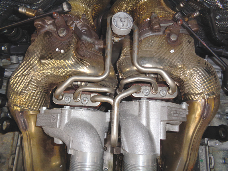
Once the air intake assembly has been removed, turbocharger removal is the next step. Begin by removing the vacuum wastegate actuators mounted toward the rear of the engine. Don’t forget the exhaust manifold bolts at the rear of the engine. These bolts are easily accessed except for the bottom middle bolts which must be accessed with a crow’s foot for best results.
The oil and coolant supply lines come in from the top of the turbochargers. Carefully remove these from the turbochargers, being sure not to kink or bend them in any way. The oil supply lines should be thoroughly inspected and cleaned before reusing. If they appear to be blocked or damaged, always recommend replacement. Oil supply blockage is a killer!
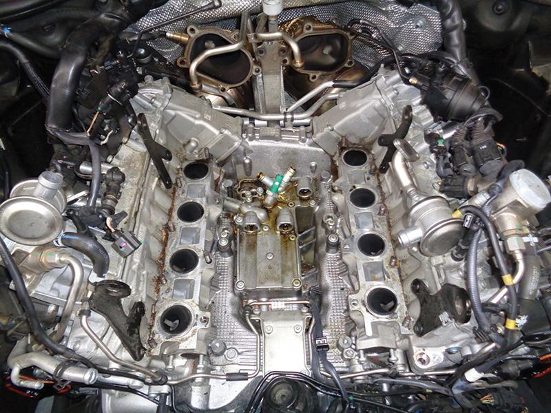
With direct access to the oil module in the valley, now is the time to remove the cover and inspect the oil supply screen. These are usually partially to fully blocked. Always check and replace this screen during turbocharger replacement. Failure to do so will result in an expensive comeback repair. Audi also recommends replacing the oil control check valve located in the oil module during turbo replacement.
With intake and exhaust manifolds and coolant and oil lines disconnected from the turbochargers, they are ready to be unbolted from the cylinder head and removed. Be sure to replace exhaust manifold hardware and gaskets as well. When fitting the new turbochargers, always prefill the oil feed at the turbo. This can be done by slowly pouring in fresh clean oil. This ensures instant lubrication on the initial start-up. After initial start-up, always let the engine idle for a few minutes to ensure that proper oil pressure reaches the turbochargers before increasing engine speed.


0 Comments