
The OBDII Fuel Trim DTCs P0170 and P0173 are often the subject of robust online debate, some confusion as to their meaning, and further debate as to how to solve these faults in Mercedes-Benz vehicles. As most of us are aware, the generic OBDII DTC (Diagnostic Trouble Code) structure is governed by standards, meaning each manufacturer must meet the generic standard by associating emissions-related DTCs to the (available and pre-determined) generic DTC code sets.
In the case of OBDII codes P0170 and P0173, it is important to note that the OBDII standard does not dictate which of these various code sets must be used to (first) identify a fault; how the manufacturer arrives at the compilation of data, engineering units or scaling; nor the scope of parameters analyzed and used by the OEM as criteria to set the fault. In general terms, the standard only requires that, in the end, the emissions fault must be able to be translated and communicated over the standard’s approved data exchange protocol and that the fault can be identified, tested and corrected within the standard’s guidelines.
So what’s the big yank then, you might ask, regarding the differences between diagnosing the P0170-P0173 DTCs, versus the P0171-P0174 Lean Bank and P0172-P0175 Rich Bank DTCs? Is there actually a substantive difference between the code sets and what they mean in our diagnostic path and approach to solve the fault?
These two different, yet closely similar, sets of codes both clearly indicate some sort of control issue related to unfavorable rich or lean engine conditions. There is certainly no shortage of debate, opinions, guesswork, and misinformation on the subject readily available with a quick internet search.
There are also it seems, are no shortage of “smart†DIYers who are willing to throw a few cool hundred-dollar bills at sensors, ME modules and other parts cannon shots in their quest to “save money,†before we inevitably get the vehicle in our bays, only for the same to complain about the cost of diagnosis. Same thing, only different, argue some techs and DIY info-seekers on the online forums. Lean is lean. You say “potaytoes,†I say “potahtoesâ€â€¦ Exactly. But… Is this debate just a red herring? Let’s dig in and see.
To the author’s understanding, the setting of the P0170 and P0173 DTCs would likely have to be predicated on set enable criteria that is plausibility-based. For example, the pre-programmed rich or lean adjustment limits have been exceeded, based on truth tables programmed into the software, whereas the set enable criteria driving the P0171-P0174 and P0172-P0175 codes are derived directly from Oxygen Sensor or Air-Fuel Ratio (AFR) monitor performance.
In the generic OBDII DTC list with generic code descriptions, the P0170 code description is “Fuel Trim Malfunction, Bank One†and P0173 is described as “Fuel Trim Malfunction, Bank Two.†Pretty darned generic. So why focus on this distinction here if they indicate pretty much the same problem? Because much of the confusion surrounding these DTCs is unnecessary; for although these code combos appear to be near mirror images of each other, in that they both call out a fuel control fault, they are not alike at all. But if we read the clues, including what the codes are telling us and the reasons why each code sets, it all starts to make sense why those Mass Airflow Sensors usually solve the issue.
In European applications, such as is the case with Mercedes-Benz vehicles (like the W203 chassis for example), the P0170-P0173 combo can often be seen first, rather than the omnipresent P0171-P0174 combo which are more commonly seen first in US Domestic and Asian applications. The funny thing is, both DTC combos essentially point the technician toward a similar thing, a fuel control fault, only the code descriptions are worded differently. For example, in most Euro applications, depending on scanner interface used, you’ll notice P0170-P0173 will be described as something like “Rich Correction Limit Exceeded†or “Rich Adaptation Limit Reached.â€
In simple diagnostic terms, this DTC would typically be flagged by the Motor Electronics (ME) module when the total allowable fuel trim correction programmed into the fuel control software has essentially hit its wall, and the software (key word) deems the fuel control system to be at its maximum self-adjustable (rich, in this case) limit. However, if you also consider the typical OBDII set enable criteria for the P0171-P0174 combo of DTCs, it is the thresholds for the amplitude and/or direction of O2 voltage or AFR current in relation to the oxygen content in the exhaust stream that is used to monitor and trigger the P0171-P0174 and P0172-P0175 faults.
So, is there a measurable distinction between the two code set combinations, and if so, how would we go about (1) isolating the fault and (2) reasoning whether (or not) this is a fuel or air related issue? Can the distinction between these two code sets provide any clues?
Consider that throughout the various Mercedes-Benz chassis deployments, engine control developments and system advancements over the years, the meaning or diagnostic direction associated with these fuel trim codes has not really changed much over time. In the field, many techs will agree that in a large percentage of cases, a MAF cleaning or replacement is stated to have been the overwhelming fix for the P0170-73 codes on Mercedes-Benz vehicles over time. Is there a clue here? Maybe, if we read the tea leaves.
Considering the realities, which is that whether the ME module is flagging the 0170-0173, or the 0171-0174 string, we are dealing with some sort of a rich/lean adjustment limit due to a lean/rich condition, or more accurately a perceived lean condition. Could the ME module be fooled into believing that there is a lean condition, when one does not exist? Yes, it certainly can, which is our red herring. In the case of the 0170-0173, the ME is reporting that it can no longer adjust, the limit has been reached. Ok, but if this was being caused by an actual fuel control issue, wouldn’t we see the 0171-0174 codes set instead? Maybe.
If we think about it though, any rich or lean type of a DTC would demand a somewhat focused look at whether it was a fuel contribution issue or an air contribution issue, right? So what are a few quick tests that can help to isolate the source of the fault quickly and accurately? If we apply a “Split the System†(air side from fuel side) approach and thought process, in other words assess why the code is setting and then apply a little physical testing in the form of sensor data analysis, mechanical analysis and diagnostic thought, then we can deal with these common fault codes a bit more confidently.
Diagnostic Focus: Air, Fuel, or Red Herring?
With P0170-P0173, it makes sense to focus on the air side first, as these codes are likely to be plausibility-based. It could also be presumed that the O2/AFR monitors would report a fault in the O2 or AFR sensors.
In our experience, we have found that a most of these codes are indeed solved by MAF replacement. It only makes sense here that the problem with the fuel control system does not show up in the O2/AFR driven fuel trim activity, other than the fuel trim steps or jumps up along with the RPMs and load, but at this point, the fuel trims can correct via the O2 control, hence no P0171-P0174 setting.
How could we see this using graphed data? Figures 1 and 2 are a representation of a vehicle bay test, where the ratios of two critical measurements help to split the system into air versus fuel. The green line shows RPM changes from idle to 4000 RPM in several steps, the red line indicates the ratio of MAF to RPM changes, as the engine is throttled, and the blue line shows the ratio of total fuel trim to RPM changes as RPMs increase.
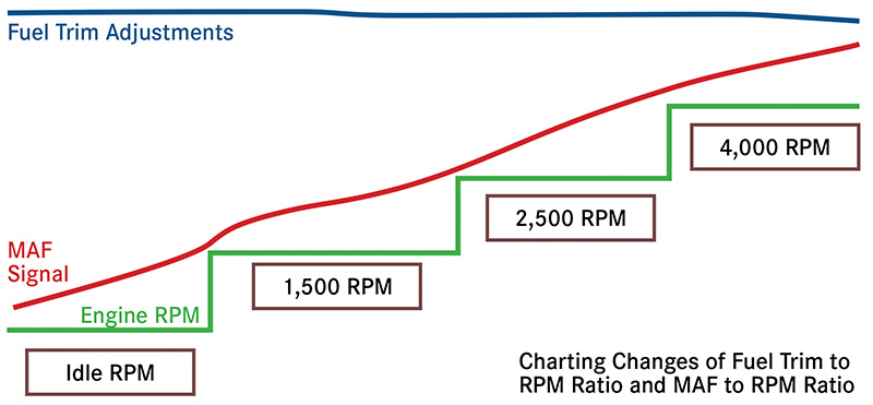

Here are the physical rules of thumb at play here when all is well: First, MAF should always proportionately increase with RPM and load, and second, fuel trim correction to RPM load increase should be a smooth, almost linear adjustment to maintain stoichiometry. Both of these rules of thumb are represented as working normally in Figure 1. Figure 2 shows a case where the fuel trim is changing dramatically with RPM and the MAF signal is all over the place. If we chart this data, or overlay it live while the engine is under test, we can often “see†or isolate the air or fuel direction of our diagnosis quickly.
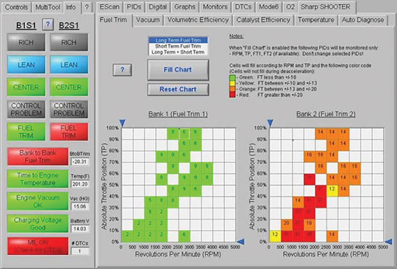
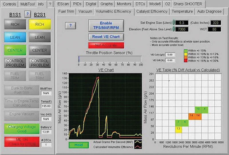
In our shop, we have enough business to easily support a XENTRY Diagnostics machine. But just as a special tool could be more useful than a generic, we use some specialized aftermarket tools to help us with diagnosis. In cases like this, the ATS Escan Elite tool that we use does a great job isolating the problem by splitting the system between an air-side fault or an actual fuel control or supply issue. The fuel trim test shown in Figure 3 and the VE/MAF test shown in Figure 4 display the actual fuel trim activity in each block of the RPM/Load range. This is a handy tool that could also be done using spreadsheet analysis and/or live sensor overlay, but the Escan gives us the answer in seconds, with a brief road test and two easy test recordings.
Perceived Lean Conditions, AKA Red Herring
In the case of the P0170-P0173 being the only DTCs set, it could be argued that we are likely dealing with only a perceived lean condition, where the ME module is detecting that the rich adjustment limit has been reached. However, we need to note that there is no indication from any other control sensors that an actual mixture condition exists. Otherwise we’d very likely see the specific P0171, 0172, 0174 or 0175 codes or other mixture-related faults, right?
These are the insidious problems that can creep into a technician’s day. You would think that if the vehicle was going to set a code for some sort of a lean fault or rich correction fault due to the MAF signal being off at any given point, it would set a MAF fault code, right? Not so fast. There are many documented cases where the MAF signal was off enough, especially off idle and with increased engine load, to cause faults and driveability issues, and yet the vehicle never sets a MAF fault code.
This means a careful data analysis of Volumetric Efficiency (VE) against the live MAF signal, or the ratio of MAF/RPM and fuel trim/RPM via a VE test spreadsheet is necessary: No matter how you decide to actually do it, this testing is critically important to avoid running yourself in diagnostic circles.
GDI Engine Depositing and Intake Fouling
And then there’s the discussion on how many of these codes have been solved by cleaning the intake manifold runners and decarbonizing the valves after the MAF was replaced. Why? It’s that “False Lean†thing again. Once air flow is interrupted and restricted enough with the deposits, again, things do not compute. The MAF says one thing, the engine’s programmed “truth tables†say another.
The late model Gasoline Direct-Injection (GDI) engines are incredibly dependent on the engineered “tumble and swirl†characteristics for charging air; interrupting this finely engineered combustion balance with layers of carbon in the intake and globs of oil and fuel-based carbons on the intake valves (the subject for an entire series of articles itself) has been proven to produce these kind of “Red Herring Faults†in many GDI applications across the industry. So when all else tests good, and you still don’t have an answer, get that borescope out, take a few things apart and have a look. On our support line, we find that after some analysis a simple de-carbon service restores the proper balance and cures the fault.
Camshaft Timing Faults
Shifting gears a little, a cam timing issue can indirectly cause the P0170 and P0173 codes to set too. If the air pump (engine) isn’t ingesting, processing and exhausting as it should, in other words exchanging the gasses at the right time in relation to the piston’s TDC and degrees of crankshaft rotation, the engine can be lean mechanically, yet the fuel control system can continue to adjust for it. But only to a point.
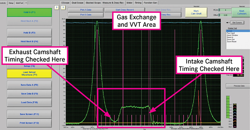
Most cam timing codes across the industry are set to flag a DTC somewhere between 10 and 20 degrees from target, and if we have a stuck cam-phaser adjuster, a loose timing chain (but not yet “jumpedâ€) or an oil pressure problem in the tensioners, VVT control solenoids, camshaft or phaser’s oil feed and drain circuits, we could also potentially see this code set. To diagnose whether a mechanical fault is in play, we like to use the in-cylinder pressure waveforms. It can also be handy to compare triggered exhaust and intake vacuum waveforms to pinpoint the cause of the mechanical fault before disassembly of the engine for inspection. Refer to Figure 5 for measurement area identification of the in-cylinder waveform.
Of course, whenever faced with any code series indicating rich or lean conditions, correction limits reached, etc., we must go back on basic rich-lean diagnostics from time to time as well. Personally, unless directed to do so by a given DTC or lack of other supporting data, I don’t usually bother with a fuel pressure test if we are not seeing the corresponding crazy fuel trim adjustments. You cannot have a low-pressure fuel supply issue without a corresponding actual lean condition and the associated excess in oxygen, confirmed by an actual low voltage on the O2 sensor or lean indication on the AFR.
General Checks
Smoke testing, checking for vacuum leaks, inspecting and testing for unmetered air leaks in the MAF piping, etc. may all still be necessary to solve the codes in the long run, but not usually. Most experienced technicians, particularly European car technicians, already inspect for this as a matter of course, as unmetered air has always wreaked havoc with electronic fuel control systems.
Catching that Red Herring: Scope Testing the MAF Sensor and Scan Data Analysis
When the MAF is suspected to be at fault, a great way to catch and verify this quickly is to snap test the MAF while monitoring the signal on an oscilloscope. In a typical Analog MAF/ECU relationship, the amplitude of the sensor signal will reach about 4.0-4.2 volts, indicating that it is reading and reporting all of the air going past it. If the MAF voltage struggles or cannot reach to 4.0 (e.g., readings like 2.8, 3.2… 3.4 volts at the top of the second deep snap), the sensor is NOT capable of reporting all of the air entering the engine, and this confirms your P0170-P0173 code.
If we have a MAF that fails the 4.0V snap test, we always start by cleaning it and repeating the snap test. If the sensor makes 4.0 volts, or at least has dramatically better resolution, we replace the sensor. We have found that putting the vehicle back on the road with a “cleaned†MAF almost always comes back to bite you later as a “comeback†and the MAF will need to be replaced anyway, so avoid the comeback and replace the sensor if it first fails then passes this scope test after cleaning.
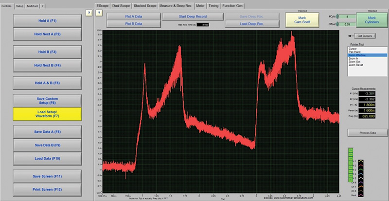
To capture this test in a usable waveform, I set the scope to a 1 or 2 second sweep, so if your scope is set to adjust and display the sweep speed in PER/DIV (per division on the graticule) increments, use the 50 to 100 ms per division setting, depending upon how many graticule divisions your scope displays.
Always remember to measure the PEAK of the second snap throttle. This is due to the fact that on the first snap, the engine is just spinning up to higher RPM from off idle, so during that first snap, the engine is not going to ingest its maximum amount of air. After the first snap, let your foot off, then immediately perform the second deep snap without letting the engine idle down. If you do two successive deep throttle snaps, you will notice the second time (because the engine is already “spun upâ€) the engine will ingest it’s maximum peak of air intake and the MAF will measure it.
In summary, the P0170 and P0173 codes seen more often in European applications are indeed a different set of codes than their P0171-P0174 cousins and provide us all the info we need to quickly test and repair the fault. That is, if we can test with focus, read the tea leaves clearly and get through the red herrings strewn along the path! Until next time, enjoy your summer!


0 Comments