
The features of the M274 (and similar M270) 4-cylinder engine, with maintenance needs and procedures
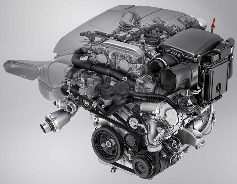
Introduced to the United States in the Model 205 C-Class in Model Year 2015, the M274 4-cylinder engine joined its year-old sister engine M270. While our focus will be on the longitudinally-mounted M274 intended for rear-wheel-drive vehicles, the transverse-mounted M270 is essentially the same engine, and much of this information applies to both. While not as widely installed as the big brother M276 and M278 engines, there are still millions of these engines on the road worldwide, many of them needing to visit your shop for maintenance and service.
Overview
The M274 is a gasoline direct-injection (DI) engine equipped with a single turbocharger. Improvements in CO2 emissions, power, torque and engine noise were the goals for the design of this M271 replacement. Intake air and engine thermal management are especially new systems, and the ECO Start/Stop function is standard equipment. In the United States, the M274 is a 2 liter engine, but other displacement variants are found elsewhere.
The DI system uses Piezoelectric fuel injectors for extremely fast and precise fuel delivery. A high-pressure fuel pump delivers up to 200 Bar (nearly 3,000 psi) and is driven mechanically by the intake camshaft. The single turbocharger is vacuum-controlled. The cooling and oil circuits are carefully regulated and controlled for better efficiency. The crankcase and oil pans are made of die-cast aluminum with an open-deck crankcase, with high-strength aluminum alloy cylinder heads. Two overhead camshafts, each with solenoid adjusters and driven by a conventional timing chain, actuate a total of four valves for each cylinder. The oil pump is driven by a separate chain from the crankshaft.
Thermal Management
The ME-SFI engine control unit (ME) closely regulates the coolant temperature in the engine. This allows the engine to reach operating temperature more quickly, which is intended to reduce exhaust emissions while improving heating performance. After a cold start, ME switches off the coolant pump switchover ball valve via a vacuum actuator, stopping coolant flow.
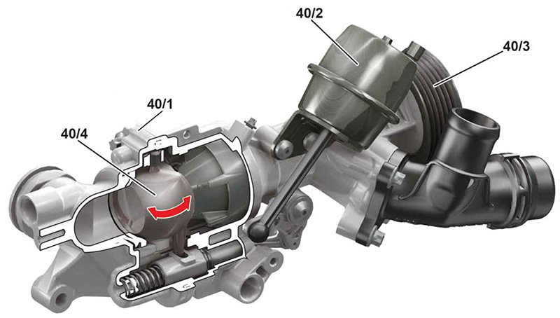
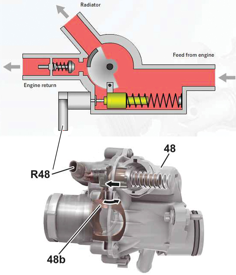
The coolant thermostat contains a heating element, activated by a ground signal from ME, which is used to control engine temperature via the thermostat. Within the thermostat is a wax element that, when heated, adjusts the position of a rotary ball valve. This allows for fine-tuning of the warm-up process while still allowing coolant to flow to the cabin heating system, as well as careful regulation of the coolant temperature to a range of 98°C to 108°C.
The Power Train Control Unit controls the electric cooling fan. Using a Pulse-Width-Modulated (PWM) signal, the fan speed can be varied from off (10% PWM) to full speed (90% PWM). The reason these values are not 0% and 100%, respectively, is to allow for diagnosis: PWM values below 10% or above 90% should never be seen, and if they are, there is a fault somewhere. If a problem is detected, the fan is commanded to maximum speed. The fan can run for up to about 5 minutes at a PWM setting of 40% after key-off to help cool the engine, but if battery voltage sinks too low, this can be suppressed. For safety, allow some time before getting under the hood.
In case of detected overheating of the engine, engine timing is retarded to help reduce heat generation. According to the specifications, this adjustment starts around an engine coolant temperature of 90°C and charge air temperature of 20°C, and depends on engine speed and load. Assuming wide-open throttle (WOT), at 100°C coolant and 20°C charge air temperatures, a 2° CKA (Crankshaft Angle) retardation is expected; while at 100°C coolant and 60°C charge air temperature, the adjustment is 8° CKA; at 125°C coolant and 60°C charge air temperature, 11° CKA is expected.
Engine Ventilation
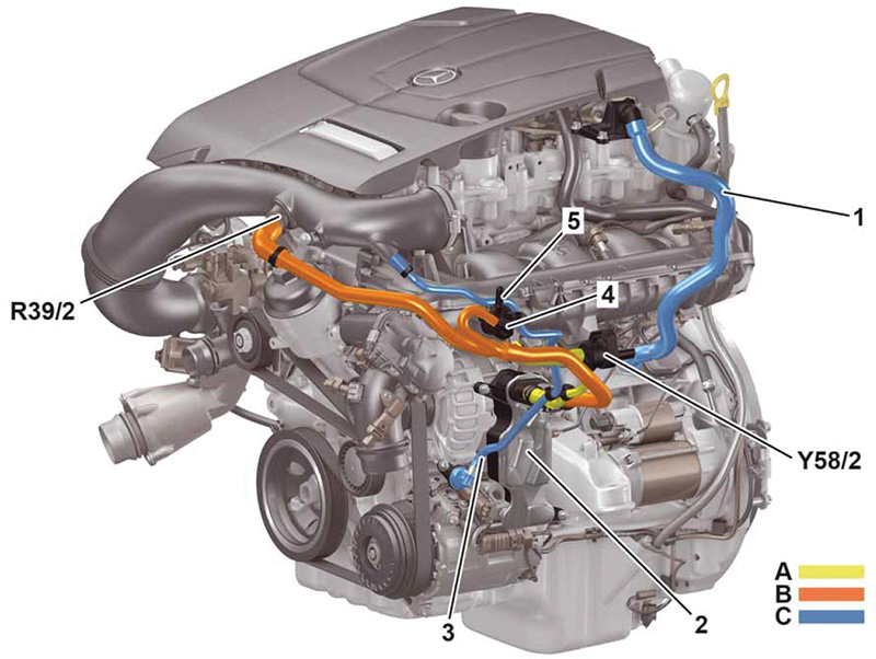
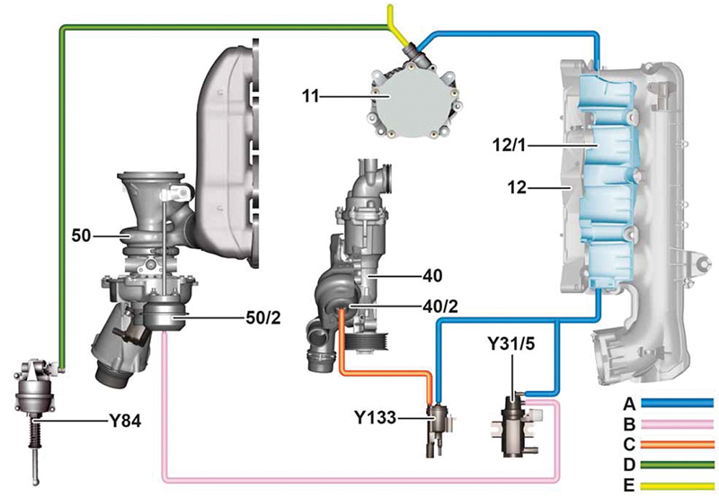
As with the M270, the crankcase ventilation is somewhat complex. The nearby image shows the hoses, connections and routing. Be aware that there have been several variants of this system, so be sure to check in the Mercedes-Benz Workshop Information System (WIS) for model-specific information and be careful to trace the lines accurately to avoid mix-ups. The M270 is similar, but components are placed differently.
Be aware that some engine ventilation components are not able to be replaced separately. Instead an assembly must be installed. To help with any costly errors, check the Mercedes-Benz Parts Information application, WIS, or ask your local dealer about which parts are available before disassembling any part of the engine ventilation system.
Basically, gases within the engine are collected and routed to the intake to be burned. At partial load, the Partial Load Operation Crankcase Ventilation System Valve (Y58/2) is opened, and gases are extracted from the oil separator at the lower front left of the engine and delivered to the charge air distributor (intake manifold). In WOT operation (when the manifold is at pressure due to turbocharging), ventilation occurs from the oil separator to the air intake pipe, using a venturi. In the WOT vent line there is a heating element (R39/2) that keeps the crankcase ventilation system from freezing. Blow-by gases are collected at the oil filler neck, via a passage in the crankcase to the oil separator. A purge valve handles fuel tank ventilation needs.
Between the oil separator and the WOT vent line, there is a connector that is destroyed when disconnecting and must always be replaced. To remove it, cut open the rubber lining and position a flat-blade screwdriver at the predetermined fracture point. Twist to break open the sleeve.
Chain Drive and Camshaft Adjustment
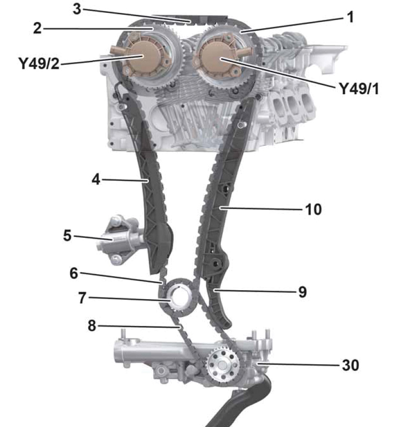
If you are familiar with other Mercedes-Benz engines, this system will be familiar, so we’ll just touch on it. Intake and exhaust camshaft angles can be varied about 30° CKA (intake, advanced) and 40° CKA (exhaust, retarded) using solenoid adjusters. A 150 Hz PWM signal from the ME controls these solenoids using a characteristic map in the partial-load and WOT range. Hall sensors monitor camshaft angles and report this back to the ME as a variable voltage. In this way, variations between commanded angle and actual angle are sensed and, in case of a mismatch, a Diagnostic Trouble Code (DTC) may be stored.
Removing the cylinder 1 ignition coil and the camshaft Hall-effect sensors allows you to check the basic timing. Look in WIS for the exact procedure. Do this any time you suspect a valve timing issue or see a related DTC.
Engine Air Supply
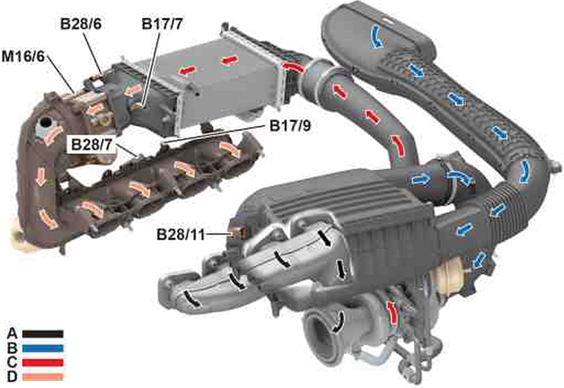
To help engine efficiency, an air intake path needs to have a low resistance to air flow, yet maintain favorable flow conditions under all possible circumstances. Intake air is passed through a relatively large air filter to minimize flow resistance and is delivered to the cold side of the turbocharger. The expelled exhaust gases drive the hot side of the turbo and cause the incoming air to be compressed. This air, heated by the act of compression, is cooled as it passes through the charge air cooler. In cars, the charge air cooler uses the low-temperature (liquid) coolant circuit, while in the Metris van, an air-to-air charge air cooler (mounted below the coolant radiator) is used. From there, it enters the engine via the charge air distributor pipe at a pressure of about 10 psi.
As a side note, in the Mercedes-AMG high-performance cousin of this engine, the M133 uses a similar system at a boost pressure exceeding 25 psi to extract more than one horsepower per cubic centimeter of displacement.
As is typical in a turbocharged engine, the intake manifold is not a reliable source of vacuum, so an engine-mounted vacuum pump is used. Although the days of vacuum-actuated climate control systems are long gone, vacuum is used for the brake booster, the boost pressure control flap, and controlling the coolant pump, for example. A vacuum reservoir is integrated into the molded charge air distribution pipe.
For the full-load crankcase ventilation system, the intake pipe has a small narrowing (venturi) to produce limited vacuum. At low or partial load, when the turbocharger is not producing appreciable boost, the charge air pipe also has a limited vacuum.
Fuel Injection
The Piezoelectric fuel injectors allow for very precise fuel delivery, again to help manage fuel economy and emissions. The fuel feed line is sealed at the high-pressure end by a sealing unit consisting of an O-ring and anti-extrusion rings. The seal between the fuel injector and cylinder head is a Teflon ring. Any time an injector is removed, it is absolutely critical that the WIS instructions for reinstallation are followed closely, particularly concerning the use of the special tools for this job, to ensure a leak-free installation. All seals and the hold-down spring must always be replaced. Never use a slide hammer, since the rail is soldered, and both the rail and injector will be damaged.
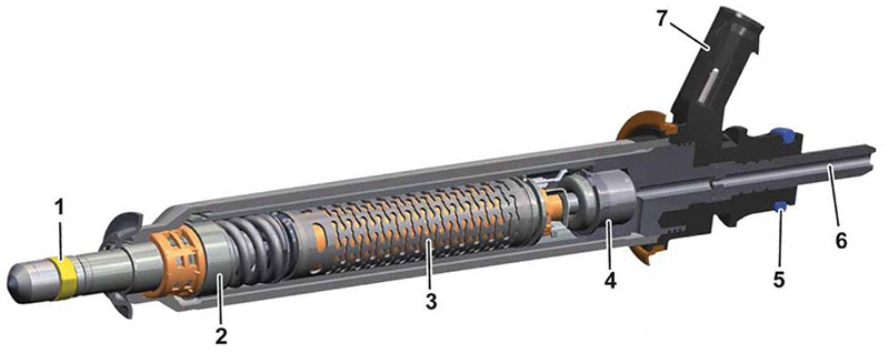
During operation, the injectors operate at voltages between 125V and 210V and a current of up to 8 amperes, which can be fatal if contacted by the body. Never expose yourself to these voltages by, for example, attempting to measure them directly as opposed to using a contact-free current clamp. If the ignition must be switched on, do not touch any part of the system or testing instruments/probes while energized. Accidentally shorting either injector control wire to ground will damage the ME, and accidentally reversing the polarity of the wires will damage the injector.
The injectors themselves are fragile, as the piezoelectric elements are similar to thin glass. Never apply a voltage to a piezo injector, as it will be damaged. Dropping an injector or subjecting one to any kind of shock (such as a hammer blow) will destroy it, requiring replacement. Any contamination of either end of the fuel injector will also damage it, so always use clean protective caps at every removal.
Lastly, the high-pressure side of the fuel system (which includes the injectors) can remain at over 200 Bar (3,000 psi) for a very long time after the engine is switched off. Use extreme care in depressurizing the system prior to repair work to avoid having fuel penetrate your skin under pressure, which can be fatal.
Ignition
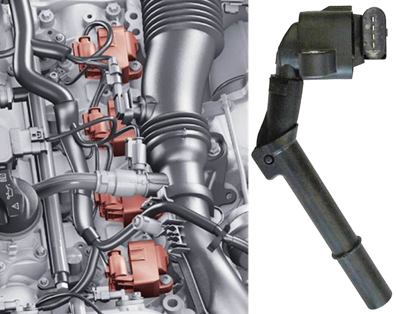
In a conventional engine, the ignition system generates a single pulse for the spark plug to ignite the combustion mixture. The M274 family of engines operates in both single-spark and multi-spark modes. Initially the same as a single-spark cycle, in a multi-spark cycle the ignition coil energy is not fully discharged, but is recharged in the interim so it can again provide enough energy for additional sparks. These multiple sparks allow for a slower, yet more complete combustion, increasing fuel efficiency while reducing emissions and engine noise (particularly after a cold start and during the warm-up phase).
Each spark plug has its own coil. The spark plugs are connected to the coil by a short boot. The ME controls each coil through individual direct connections. The ignition coils also deliver diagnosis information back to the ME through the same wire.
Maintenance
Vehicles equipped with the M274 (and M270) engine are equipped with the Mercedes-Benz ASSYST PLUS system. As always, check the owner’s maintenance booklet or the maintenance sheet in WIS or STAR TekInfo for the most accurate information, but in general these engines need an oil and filter change every 10,000 miles (or one year). The engine oil dipstick is used to check the oil level.
As with virtually every vehicle, the maintenance sheet also calls for engine air filter replacement every 40,000 miles (or 4 years) and fuel filter and coolant replacement at 120,000 miles (or 10 years). Check the maintenance sheet for a complete rundown of all the required maintenance points.
Service Notes
Aside from those already mentioned, a few service tips might help save some time.
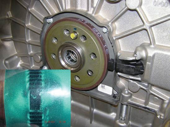
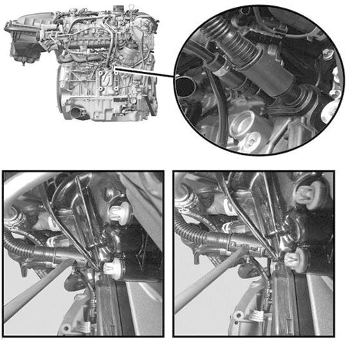
The crankshaft position sensor is mounted near the flywheel, but it cannot be placed straight into the opening. Instead, it needs to be guided ‘around the corner’ and into a slot. See the nearby image showing the ‘hidden’ part of the sensor mounting. Instead of sensing flywheel tabs or slots, a magnetic ‘increment wheel’ is used. The increment wheel is fragile and can be damaged by rough handling, metal shavings or exposure to another magnet.
When checking ignition angles, the only possibility is to use XENTRY Diagnostics. The ignition angle cannot be measured with conventional tools and equipment.
When working on the injectors and fuel rail, the stainless steel lines can be reused as long as they pass the test as specified in WIS. At over 200 Bar, you don’t want a leak, so if you’re not sure, replace it.
Use only genuine Mercedes-Benz spark plugs. Aftermarket plugs are not always indexed, meaning the electrode gap needs to be facing a specific direction. Install incorrectly indexed plugs and the M274 will, as with the other Direct Injection engines from Mercedes-Benz, suffer from melted or cracked pistons from incorrect combustion patterns. If you haven’t read the article on spark plugs in the March 2021 issue of StarTuned, now is the time to go look at it.
Connected in parallel with the ME’s piezo actuator module is a 200 Ohm discharge resistor. This value can be measured on the injector plug after disconnecting it from the injector. Be absolutely certain the ignition is off and the key is in your pocket, since this connector carries dangerous voltages when the ignition is on.
It probably goes without saying, but we’ll say it anyway: All work around the fuel system must be surgically clean, since even the slightest speck of dust can ruin the system.
While beyond the scope of this article, the M274 is also installed in vehicles equipped with 4MATIC. These models have a conventional transmission/transfer case arrangement, while vehicles with M270 have a very different setup due to the transverse mounting. Check in WIS for those details.
One Last Thing
We often refer to the Mercedes-Benz Workshop Information System for ‘more details,’ but not because we want to leave you in the dark. In fact, except for the simplest of jobs, working without WIS often leads to frustration, broken parts, incorrect (or even unsafe) repairs and just a boatload of trouble. If your shop already has a subscription to WIS (part of STAR TekInfo) you know its value, but in our travels we meet shop owners and technicians who don’t use WIS, often saying “it’s too expensive.â€
All we can say is ‘give it a try.’ Working without WIS is working blind.
Visit startekinfo.com and select the application (passenger cars, commercial vans, or ISPPI parts catalog). Hundreds of documents are available for free, without registration, but if you want a full subscription, just either log in (if you already have a “C7†user ID) or register as a new user. Once you’re logged in, there should be a “Subscribe/Renew†button on the top right. Click that and follow the instructions. If you end up on the UMAS page, you’re headed in the wrong direction: Go back to the home page, log out and start again.
We hope you found this article about the M274 engine informative and practical. We covered some of the newer systems and functions, and offered some of the more common service tips we’ve come across in our work. If there’s something you’d like to see in StarTuned, please drop us a note. We’d love to hear from you!


0 Comments