
Unlocking the Mysteries Behind Gasoline and Diesel Piezoelectric Injectors
I recently read David McCullough’s book The Wright Brothers about their work as pioneers of aviation. One interesting fact was that they built their own engines, and the very first engine they successfully flew had no carburetor; apparently, they just engineered it so the fuel just “dumped” into the air flowing through the intake. I assume they rigged some way to regulate it but I don’t recall any mention of how so. It would be a stretch, but you could call that system an early prototype of fuel injection!
Although many sources indicate various claims to the very first use of fuel injection, suffice it to say that we’ve certainly come a long way from the early days. In 1936 Daimler-Benz began mass production of the precombustion-chamber-injected Mercedes-Benz OM138 diesel engine, one of the first passenger car engines with fuel injection. The world’s first gasoline engine with direct injection was the legendary 1954 Mercedes-Benz 300SL Gullwing.


As a young technician working primarily on domestic models, I quickly became drawn to the import automotive market where my fuel injection training began. Carburetion and fuel injection were worlds apart, but I was fascinated by the efficient design of fuel injection.
Fuel Injection 101
Let’s take a quick review of different types of fuel injection so that we might compare and appreciate the advances and advantages of piezoelectric direct fuel injection.
First, we have single point fuel injection, where a single injector sprays fuel into a central location in the intake manifold to be distributed into all the cylinders as the valves open. This type of injection is also termed Throttle Body Injection. Although it can be an improvement over carburetion, it is still lacking in the efficiency department along with some drivability concerns.
Next, we have multi-point injection. Each cylinder has its own injector mounted in the intake manifold in front of the intake valves. The ECU is programmed to fire all injectors at the same time emitting only a fraction of the fuel required for each cylinder so that at the end of the engine cycle the sum total amount of fuel required is injected. An improvement over single point injection but still some inefficiencies as fuel is pooling in the intake for several milliseconds while waiting for the intake valve to open.
Sequential fuel injection solves the problems of multi-point injection in that the fuel is only injected for each cylinder at the precise time it is needed, thereby increasing the efficiency and improving emissions. Until direct injection, this was the most common type of fuel injection used on modern production engines.
Mercedes-Benz has a long history of fuel injection systems, including D-, L- and K-Jetronic, CIS and CIS-E, KE, LU and so on. You can read about classic Mercedes-Benz fuel injection systems in the November 2001 issue of StarTuned.
A Game Changer
The development of direct injection was certainly a game changer. Diesel mechanics have had the advantage of understanding the technology, as it has been a fundamental part of introducing fuel into the combustion chamber when Daimler-Benz switched from precombustion chamber injection to helix-controlled direct injection in the summer of 1964. Mercedes-Benz introduced at the 2005 Frankfurt Auto Show the world’s first gasoline engine with piezoelectric direct injection and spray-guided combustion. Known as the Stratified Charge Gasoline Injection (CGI) engine, the spray-guided direct injection system first appeared in a mild-hybrid concept car Mercedes-Benz showed at the Frankfurt show in 2005. The new 215 kW (292 hp) 3.5-liter six-cylinder engine entered the European market during the second half of 2006 in the CLS-Class as the CLS 350 CGI. This established an improvement of 10% in fuel efficiency over its predecessor but due to United States emissions regulations it never made it to the US market.
In 2012, a number of Mercedes-Benz models were introduced stateside with new engines that featured direct fuel injection with homogeneous charge (as opposed to stratified charge). The newer four-cylinder and V6 got better fuel economy while producing more pulling power, fairly impressive considering that increasing either power or fuel economy usually decreases the other.
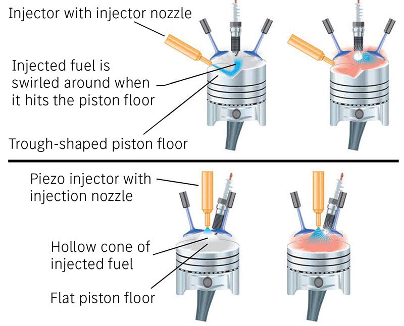
So, what is spray guided fuel injection? To help understand, you must compare the principle to wall guided injection. In wall guided injection, the fuel mixture is injected from a side angle, which hits the top of the piston and swirls around the wall of the combustion chamber. In spray guided injection, the injector nozzle is placed directly above the piston next to the spark plug, allowing the fuel mixture to stay in a more stable condition until combustion. The greatest advantage of this new technology compared to direct injection with wall-guided combustion is its significantly better thermodynamic efficiency: the fuel is sprayed into the cylinders with great precision according to engine requirements and the driving situation, where it burns almost completely with a very high amount of excess air and is most efficient.
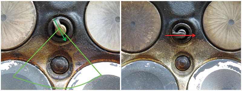
Here’s an important tip: Be sure to use only genuine Mercedes-Benz spark plugs, as the indexing of aftermarket plugs can be incorrect, leading to misfires and possible piston damage! For more details on why spark plug indexing is important, please see the March 2021 issue of StarTuned.
Let’s Get Technical
We must thoroughly understand the technology behind this enhanced injection system in order to service, diagnose and repair automobiles so equipped. Stratified charge is a word thrown around when coupled with Mercedes-Benz spray guided injection, but what is it exactly?
The principle of stratified charge operation is to deliver a mixture that is sufficiently rich for combustion in the immediate vicinity of the spark plug, while the remainder of the cylinder receives a very lean mixture that could not be used in a traditional engine. Stratified charge operation greatly reduces fuel consumption while driving under lower loads. In a stratified charge mode, the higher compression engine operates with significant excess air. Thus, the fuel is not injected into the chamber until the compression phase, after the air has been compressed by the pistons. Thanks to a highly sophisticated electronic multiple injection process, a fuel-air cloud localized in the area of the spark plug forms only at the time of ignition. This fuel-air cloud is ignited by the spark plug and in turn ignites the very lean mixture which is distributed throughout the rest of the combustion chamber. This enables extremely efficient combustion coupled with a tremendous amount of excess air.
Because the last injection takes place immediately before ignition, with the piston located almost at TDC, the requirements for depth of spray penetration and vaporization behavior are much higher than for intake stroke injection in order to prevent the moistening of pistons and walls. Also known as BlueDIRECT combustion, this process required an injector capable of distributing very short injection pulses with both extreme precision and stability.
Enter the Piezoelectric Injector
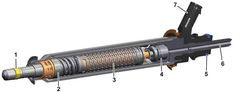
Now that engineers have found a way to get more bang for the buck in the combustion chamber with stratified charge direct injection, an injector had to be developed that could fill that need. So, what is piezoelectric and what does the word even mean? The word piezo come from a Greek root meaning to squeeze or press. The French physicists Jacques and Pierre Curie discovered in 1880 that electric charges could accumulate in certain solid materials in response to an applied mechanical stress. Using this principle, the piezoelectric injector has at its core this material, usually quartz crystal. It rapidly expands when a voltage is applied, allowing its use as an actuator for the movable pintle, or nozzle valve, in a fuel injector. A piezo injector can operate up to five times faster than a standard injector solenoid and the motion is frictionless, which allows for precise fuel measurement and multiple injection events per combustion cycle.
A piezo element only expands a miniscule amount so hundreds of slices are stacked on top of each other so that the net movement is only about .004 inches. The actual movement is microscopic, but enough to make the piezo element act as the valve. Since this movement is a downward motion, a lever and spring mechanism inside the injector allows for the pintle to open and, when the electrical signal is switched off, close. We’re also talking about a much higher voltage, enough to be harmful if contacted by a person.
After high pressure fuel enters the injector, the pressure throughout the injector is equal. Once the electrical signal causes the piezo stack to expand, the injection valve opens and the injection event takes place.
Operation and Safety Concerns
This is a high-pressure system consisting of a high-pressure pump and fuel rail, coupled with a supply pump with filter, usually in the tank. With a pressure of 130 to 250 bar (about 1900 to 3700 psi), the new system develops around 50 times the fuel pressure used in a conventional port-injection system.
Obviously, you need to be sure the system is depressurized fully before opening any connection on the high side of the system. Fuel at those pressures can be injected through the skin, and your body doesn’t take well to petroleum products. Another concern is voltage: Piezo injectors normally operate at voltages up to 200 volts, which is enough to injure you or worse.
The engine control unit generates the control voltage of around 140 to 210V and actuates the injectors with a ground signal. The piezo actuator module represents a capacitive load for the engine control unit. When opening, a current of approximately 8A flows for a few milliseconds. The control unit then reverses the polarity for opening and closing. The very short switching times of the injectors facilitate a multiple injection with short breaks during the combustion cycle.
Extreme care should be taken to protect against mechanical shock. The piezo element stack is as fragile as thin glass, so dropping or hitting it will quickly damage it. Do not touch any of the injector terminals while the engine is running and do not disconnect any connectors while running as well. Accidentally connecting either of the control wires to ground or power will also damage the injector.
Diagnosis and Testing
Before checking individual injectors, you should be guided to do so by using your XENTRY or another factory compatible scanner. If you suspect a faulty injector(s) here are some steps to take to verify a concern.
It is recommended, due to the electrical hazard, that you use certified Class-0 (low voltage) insulated electrician’s gloves rated to 1,000 volts, or better. While we can’t explain how to safely use gloves such as these, understand that they are typically used with leather or other durable over-gloves to ensure they don’t get damaged. Be sure to read and follow the manufacturer’s instructions for use, checking functionality and complying with the requirements for recertification after the expiration period. It is also recommended to wait about 5 minutes after the key is turned off, to allow the capacitors to bleed off. Don’t take these comments lightly: Your life could depend on it.
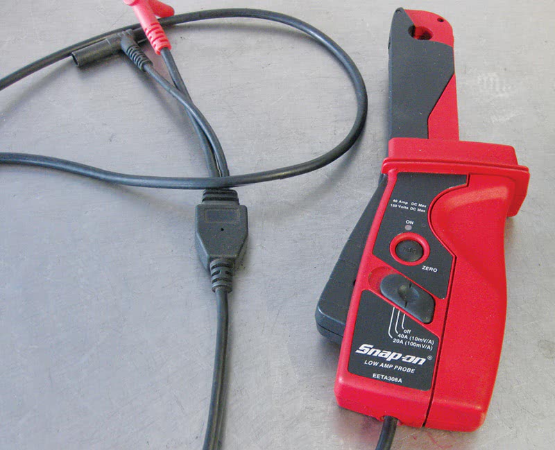
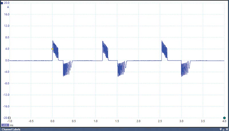
Using a clamp-on low-amp probe and a lab scope you can conduct a signature wave form test of the injectors to verify integrity. If you have a known good waveform, it is advisable to store it in the library feature of your scope. At any rate you’ll want to compare waveforms to identify any possible faulty injectors. We suggest clamping around the control-side injector wire, which typically has green insulation.
Note: The engine control module powers the input side of the Piezo electric injectors, which are linked together. Each injector in the group that receives power will see the voltage rise and stay at around 140 volts. The control side is then switched by the engine control unit to allow current to flow, actuating the injector during the compression stroke, with the on-time varying according to engine load.
However, if there is a fault in the high-pressure fuel system, the injector will open on the intake stroke as a fail-safe measure. This allows at least some fuel to be drawn into the combustion chamber, since the fuel pressure may be too low to overpower the compression in the cylinder.
Removal and Replacement
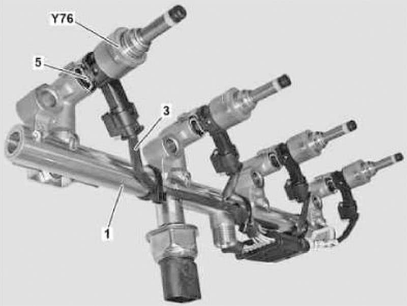
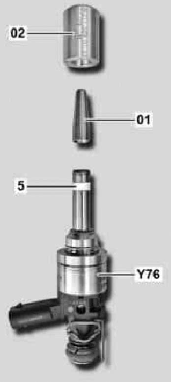
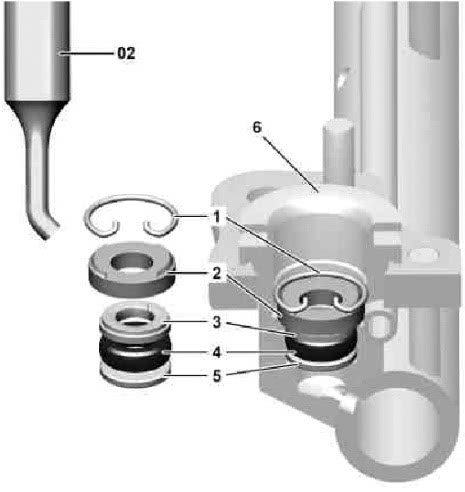
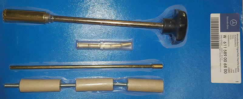
When directed to remove and replace an injector, or perhaps just replacing the seals, you should definitely consult the instructions shown in the Mercedes-Benz Workshop Information System (WIS) for the specific model you are servicing. Some models call for removing the rail with the injectors and some may be able to be removed individually. There is a handy tool for injector seal removal and replacement (W278 589 01 15 00) that can make life easier as sometimes they can be fairly stubborn to remove. Use extreme care when removing if you hope to reuse the injectors as they are fragile as glass and can crack internally. If you find you have to use a slide hammer type puller you’re definitely going to have to replace them. Also, if you find yourself reusing injectors be sure to replace them in the exact same cylinders, as each one is specifically coded and ‘taught’ into the control unit.
Cleanliness is a must and the bores should be thoroughly cleaned prior to installation. Be careful not to use any abrasives but only nylon and or woolen brushes with a chemical cleaner.
When installing or re-installing the injectors, replace the seals. There are special tools available for installing the seals in the bore for the injector as well as the seal on the injector nozzle itself. Check in WIS for the specific tool number(s) for the vehicle in your shop. The important thing is to not damage the seals upon installation, and to always use a new seal service kit available from your parts dealer. Trying to re-use either seal, or installing them without the special tools, will end in a quick comeback.
Injector calibration is a must. Each injector has a calibration code that you must teach in to the engine control unit in order for it to inject the proper fuel quantity for each individual cylinder. This is why it’s important to make sure if you are reusing injectors to return them to the same hole. There is a XENTRY TIPS article dealing with some models having a fault code for fuel injector control. The procedure, shown here, is the same as if you were calibrating a new injector:
XENTRY tips # LI07.08-P-057357 Fault code P061194—The fuel injector control unit has a malfunction (output stage fault of engine control unit)—is stored in engine control unit (sometimes with active engine diagnosis warning lamp) XENTRY Diagnostics → MED control unit → “Adaptations” tab → Select “Configuration” → “Manual settings” → “Injector injection quantity adjustment”
Check whether the entered values in XENTRY match the values on the connector housing of the individual injectors.
1. If the XENTRY values differ, overwrite them with the values on the connector housing and delete the fault memory.
Control unit replacement is not necessary in this case.
After the values have been corrected, the control unit must be reset by parking the vehicle, locking it and then leaving it in this state for at least two minutes.
2. If the XENTRY values are correct, follow the instructions of the guided test in XENTRY.
Recalls and Campaigns
One of the more important campaigns you should be aware of regarding fuel injectors is one concerning various models from 2016 -2020, “RECALL CAMPAIGN 2022030003 – REPLACE THE FUEL RAIL AND FUEL INJECTORS.” The issue is that a fuel leak can occur between the fuel injector and rail with a possible fire hazard as a result. Check your customer’s vehicles for the campaign sticker to be sure they have had this done.
Undoubtedly you’ve seen plenty of GDI and CDI vehicle in your shop already, most likely without too many problems in the injection system. Nonetheless, as they are getting older you would be wise to invest in some of the specialty tools to service them when the time comes.


Regarding the paragraph
“Note: The engine control module powers the input side of the Piezo electric injectors, which are linked together. Each injector in the group that receives power will see the voltage rise and stay at around 140 volts. The control side is then switched by the engine control unit to allow current to flow, actuating the injector during the compression stroke, with the on-time varying according to engine load.”
That reads a bit misleading, as it could lead the reader to believe that the system operates with a standard multi-point injector control, ie power supply on one wire and a ECU controlled ground on the other during operation.
But as you said earlier, the current flow through the injector is reversed to open/close the injector during operation which means both injector wires are switched/controlled.
Hi SeanMc,
Thank you for your comment. The writer of the article responded with, “Good comment, the wording is directly from WIS so you do have to pay attention to the whole article to properly understand the control.”
We hope that helps.
Best,
ATI