
Understanding the system and diagnosing P052E and associated trouble codes
They gotta breathe, right?
The concept of crankcase ventilation has been around since the beginning of the internal combustion engine (ICE). If you consider the conditions on the inside of a crankcase without considering any other factors, you have a closed environment with a fixed amount of air. The crankshaft spins and moves the pistons up and down. As one piston moves up, another moves down, so in a perfect scenario the displacement of air would be equal.
We know that the environment inside an engine is far from perfect, so let’s add in heat as a factor. When air is heated the molecules move faster. The faster molecules move, the hotter the air. As the molecules heat and move faster, they are moving apart. So air, like most other substances, expands when heated and contracts when cooled. That equals higher crankcase pressures.
What effect does that internal pressure have on seals and other components? Yeah, you already know, not good! And, we haven’t even discussed the most critical condition that affects the pressure inside the crankcase – blow-by! Even in the most efficient engines, a small amount of combustion gas “blows by” the piston rings and creates even more pressure in the engine. Undoubtedly, you have seen for yourself when a seal has blown out due to excess crankcase pressure caused by a ventilation system that has failed. Other reasons to remove the blow-by gases or hydrocarbons include:
- The presence of hydrocarbons in the blow-by gases causes premature degradation of engine oil.
- The moisture that is deposited in the crankcase as the engine cools is circulated by the pump and can affect lubrication or cause lubrication failure in certain systems and locations.
- Engine performance decreases, as the excess pressure hinders the piston’s downward movement.
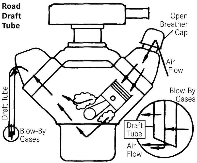
The earliest and simplest designs just had a hole in the block open to the atmosphere so that the pressure would be equalized. However, as engine speed increased, this was not enough to compensate for the combustion pressure. Enter the road draft tube. Some of us are actually old enough to remember those, or if you’ve ever worked on or owned an old classic, you know what it is. A tube was inserted into the block and bent downward towards the road, with the tip fashioned in such a way so as to scavenge the crankcase vapors out of the block as the air passed over it while driving. This actually worked quite well but there was one major problem—pollution. According to one EPA source, about 20% of the total hydrocarbon (HC) emissions produced by a vehicle are blow-by emissions from gases that get past the piston rings and enter the crankcase.
Positive Crankcase Ventilation (PCV)
The modern use of PCV is primarily for emissions reduction, but in its earliest form it was designed during WWII to allow engines to operate under water without it entering the crankcase thereby destroying it. Adding the word “positive” to the crankcase ventilation identifies it as a system that is not merely passive but proactively redirecting the dangerous hydrocarbons from the crankcase. Taking advantage of the intake manifold vacuum was a concept designed in the 1960’s and is still used today, although in a much more complicated fashion.
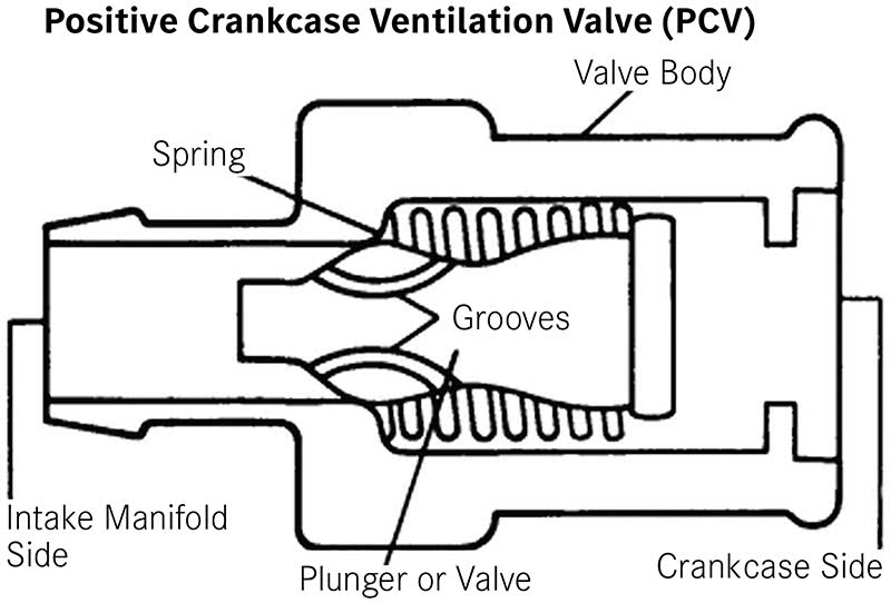
The simplest and earliest designs of a PCV used engine intake manifold vacuum to extract the crankcase vapors and introduce them into the combustion process. This idea, however, needs some sort of regulation in order to not affect the engine performance. The PCV valve was designed as a simple spring-loaded valve with a sliding pintle inside. The pintle is tapered so it will increase or decrease airflow depending on its position inside the valve housing. The movement of the pintle up and down changes the orifice opening to regulate the volume of air passing through the PCV valve. It is also a one-way valve, so that any engine backfiring won’t be directed back into the crankcase. These early designs were open systems, meaning the fresh air was introduced into the crankcase through a mesh filter in the oil filler cap or the valve cover. In 1968, closed systems were designed to further reduce emissions by placing the fresh air intake portion within the air filter housing so that any backed up gases would be sucked into the engine.
Fast Forward
Understanding the how and why of PCV is crucial in aiding the diagnosis of faults in current and recent model year designs. Automotive engineers continue to improve upon crankcase ventilation as calls for reductions in emissions and fuel consumption have an effect on the performance of PCV. One such improvement was the compensation for oil build up in the hoses and valve.
In the case of high oil temperatures and high engine revolutions per minute (RPM), an oil vapor tends to be generated. This vapor circulates through the engine breather pipes and the PCV, generating carbon in the intake system and the combustion chambers. That is why we now see various forms of an oil separator. This part serves to condense the oil vapor and return the oil droplets to the crankcase, preventing them from entering the intake, resulting in fewer carbon deposits.
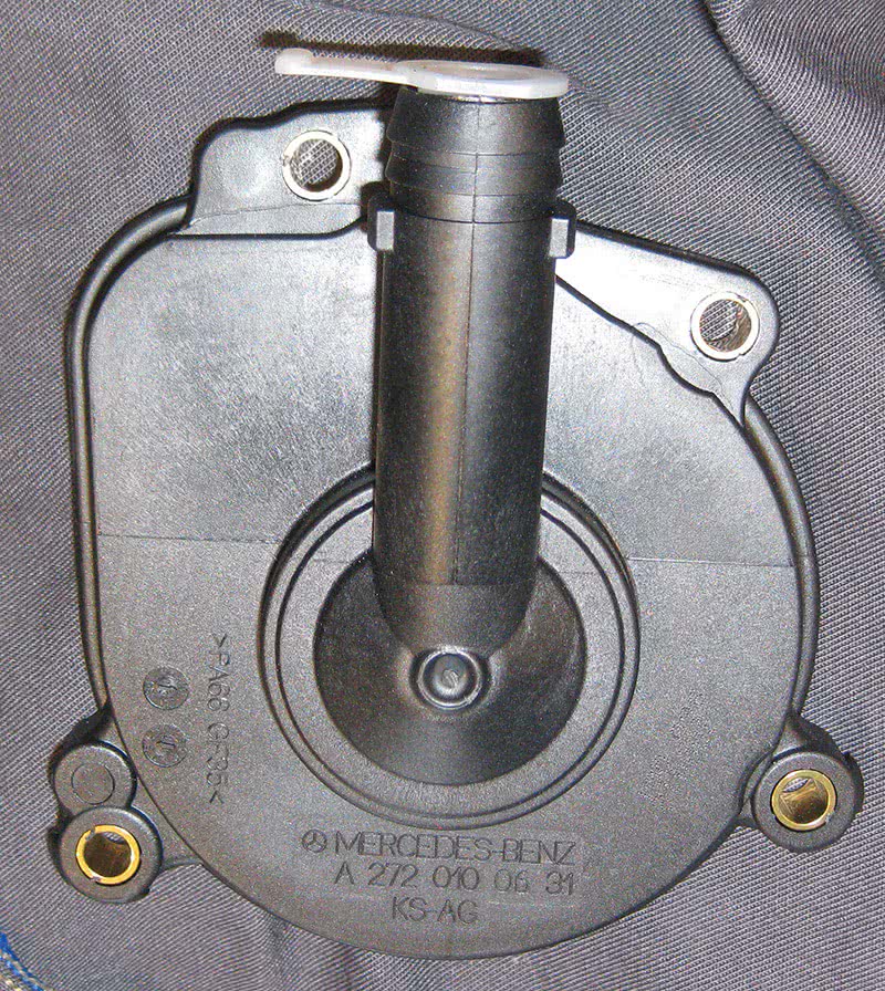
Mercedes-Benz has been using an oil separator system for quite some time and until around the 2015 model year they were fairly simple and accessible. The valve/separator would generally last until around the 120k mark, although it is advisable to check these carefully sooner. The biggest reason many are changed is due to oil leaks on the back of the right-hand cylinder head. The gasket on the cover gets brittle and leaks onto the manifold creating a burned oil smell.
Replacement of this earlier style is fairly straightforward. After removing the engine covers and air filter, reach behind the RH cylinder head and remove the valve. There are four E10 Torx bolts holding it in place. If you find access difficult, you can actually use a twelve-point 5/16″ wrench, which fits on the bolts nicely.
The new part number from Mercedes-Benz for an M272 engine is A272 010 06 31 (but please verify the correct part for your vehicle!), and it comes with the gasket and new bolts. If you are replacing this due to leakage, there are also three plastic plugs that are advisable to replace, also available from your Mercedes-Benz parts dealer. Also advisable is replacing the hoses and oil separator mounted on the valve cover. All in all, about 45 minutes to replace.
Functionality
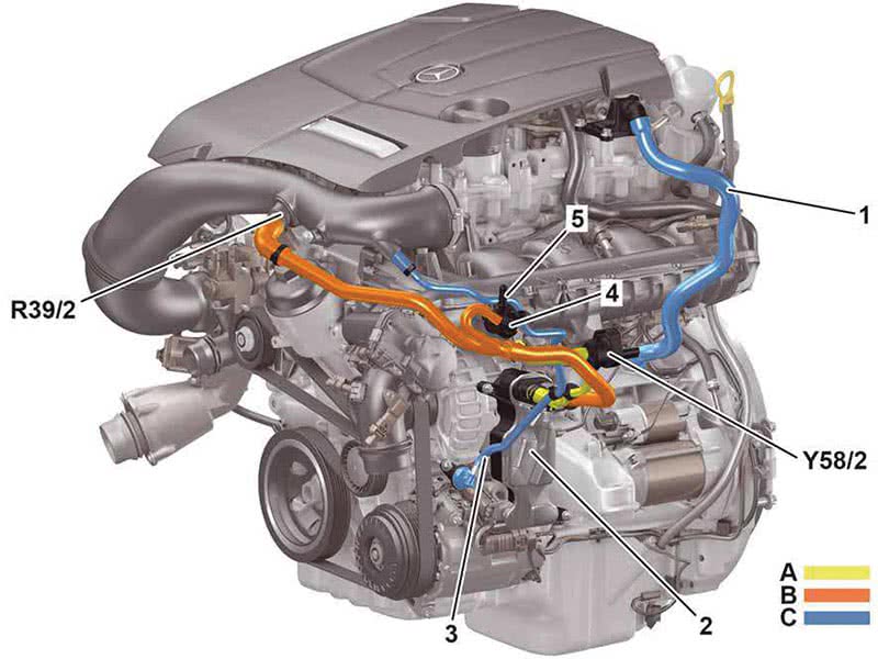
Since the title of the article infers some diagnosis concerning the P052E diagnostic trouble code (DTC), we will look more in-depth at the systems found on 2015 models and newer. Our subject vehicle is a 2016 C300 4MATIC sedan (205 chassis).
The ventilation system has the same functionality as previous models and follows the same principles as described above. Some additions are an expansion line that offsets the overpressure through the engine ventilation. The amount of air led back differs in partial and full load operation. Thinking in terms of what the engine control unit sees and what requirement it has for functionality will aid you immensely when troubleshooting any DTC’s.
Control of the venting system is dependent on the following sensors and signals:
- Pressure sensor downstream of the throttle valve (B28/7).
- Accelerator pedal sensor (B37).
- Front SAM control unit (N10/6), outside temperature via interior CAN B, electronic ignition lock control unit (N73), chassis FlexRay, powertrain control unit (N127) and the drive train CAN C1 to the ME-SFI control unit (N3/10).
- Vent line contact switch (S88/5) for some models or PZEV vent line contact switch (S88/5), again depending on model.
The function sequence has two modes of operation: partial and wide-open throttle.
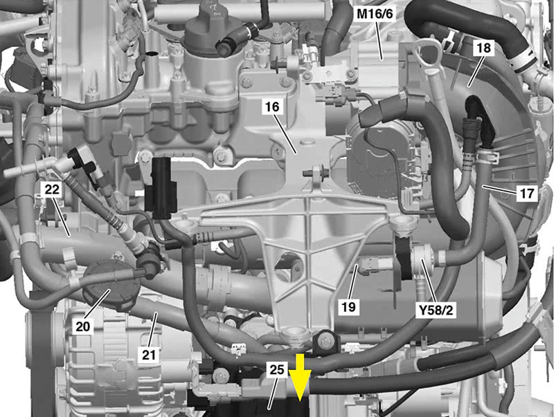
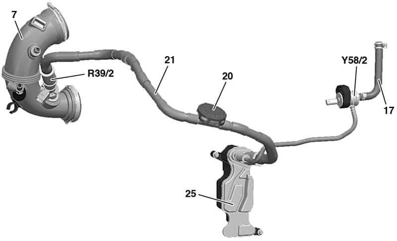
In partial load operation, bleeding is performed starting from the oil separator to the charge air distributor. To do so, the partial load operation crankcase ventilation system valve (Y58/2) is placed in the partial load vent line. The valve is actuated in deceleration mode by the engine control unit and closes the partial load vent line from the crankcase to the charge air distributor. This results in the inflow of exhaust from the crankcase during the mixture adaptation and disruptive background noise being avoided. If there is no actuation by the engine control unit the valve stays open.
In wide open throttle operation, ventilation is performed starting from the oil separator to the air intake pipe. The wide-open throttle operation vent line heater element (R39/2) is located in the full load vent line and prevents freezing of the system. The heating element is actuated by the engine control unit when outside temperatures of under 7°C are measured.
Diagnostics and Troubleshooting
Probably the most active DTC that you will encounter related to this system is a P052E—Positive Crankcase Ventilation Regulator Valve Performance actuator stuck, and its related codes: P052E11 the valve for crankcase ventilation has a malfunction. There is a short circuit to ground. P052E12 the valve for crankcase ventilation has a malfunction. There is a short circuit to positive. P052E13 the valve for crankcase ventilation has a malfunction. There is an open circuit. P052E71 the valve for crankcase ventilation has a malfunction. The actuator is blocked.
In this sample the “Positive Crankcase Ventilation Regulator Valve Performance actuator stuck” is the concern. Proceed with these steps:
- Verify engine oil is not overfilled. A major cause of crankshaft vent valves sticking is overfilling of the crankcase.
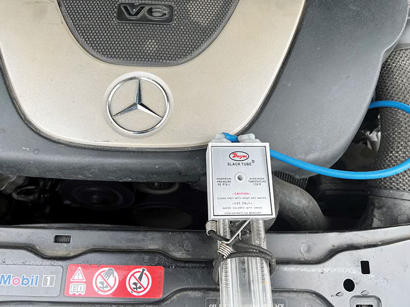
- Connect a slack tube or U tube manometer to the dipstick tube.
- Using XENTRY or a factory-compatible scan tool, actuate component Y58/2 (passenger car) or Y136 (Metris van) which is the partial load operation crankcase ventilation valve. During activation and deactivation, the vacuum drops by about 5 to 10 millibars (or hPa).
- If you see no change in values, you’ll need to access the valve to test it manually.
- Measure the solenoid’s resistance. The measured value must be between 28 and 38 ohms. Replace the assembly if outside of specification.
- With key on and engine off, verify 12 volts on the Red/Green wire.
- With solenoid exposed, activate it again with scan tool and monitor the Yellow/Grey wire for duty cycle to ground.
- If it fails to mechanically open and close, yet has correct power, ground and duty cycle actuation, you should replace the assembly. Mercedes-Benz has an updated package that must be replaced as a unit.
- If the solenoid functions, verify that all PCV hoses and passages are free from blockage or damage.
About manometers: The U tube manometer is an extremely accurate way of measuring crankcase pressure/vacuum. Since crankcase pressure/vacuum is so slight, your normal vacuum gauge is not precise enough. Many years ago, our shop purchased one and it has been a life saver in diagnosing crankcase pressure issues properly.
Note that solenoids can tend to be sticky and intermittent. If you find it working properly, try to put some stressors on it, heat and cold. XENTRY Diagnostics and some factory-compatible scan tools will provide you with a step-by-step procedure if you pull the P052E trouble code.
According to an ISP repair website, the most common occurrence of these codes happens between 50k and 100k miles. This would lead one to consider being proactive and start recommending a replacement service at the 50k mark. Considering there is an updated assembly this would be the proper recommendation.
Be aware that there are numerous websites that promise to sell you the individual parts without buying the entire assembly. This is not advisable and will only get you into trouble. Only buy the genuine article from your local Mercedes-Benz parts department. You will be assured of providing your customer with the best possible repair/maintenance quality they have come to expect from you.
Labor Intensive
Having said we should be proactive, it should be noted that this isn’t the old routine maintenance 20-minute PCV valve replacement. Expect to spend anywhere from five to six hours on replacing the oil separator and assembly. If it’s your first time around, you would be well-advised to plan on the latter.
You should carefully follow the steps in the Mercedes-Benz Workshop Information System (WIS) for your specific model, but here is a general order of R&R for replacing the vent assembly on the subject vehicle.
What most technicians advise is to purchase the assembly and have it in front of you, or on the bench, so you can have a visual idea as to what to disconnect and/or remove.
- Remove all upper and lower engine covers.
- Disconnect battery ground and remove air cleaner assembly.
- Unscrew cap from expansion reservoir and relieve pressure in low-temperature circuit as well as the cap from the engine cooling system expansion reservoir.
- Remove charge air intake manifold from exhaust gas turbocharger along with charge air cooler and place to the side with attached coolant lines. This will entail also removing the engine control unit with bracket.
- Unbolt alternator and move aside as well as the air conditioner compressor. You should be able to leave the hoses attached.
- Support the engine and remove the LH engine mount and mounting bracket. The oil separator is behind the bracket.
- Make the necessary disconnections, unbolt the oil separator from the block and replace the assembly.
- Reassembly is pretty much the reverse of disassembly. Clear trouble codes and check for any software updates.
Obviously, this is not your run of the mill crank vent valve replacement. Once you’ve done one or two you will drastically improve your time replacing the assembly. Advise your customer about the importance of regular oil service and to be sure to not overfill the system. Checking on this important system at each service as the vehicle ages is the key to preventing an annoying check engine light and P052E code. After all, your customer is depending on you to know about their vehicle and proactively identify issues, maintaining the safety and reliability they’ve come to expect.


0 Comments