The data being shared on the CAN is useless until interpreted and utilized by a Signal Acquisition Module.
A previous StarTuned article has already explained a thorough overview of Mercedes-Benz CAN bus systems and their operation. At the risk of repetition, we think a brief review of CAN bus is in order so we might give you a more complete understanding of the SAM (Signal Acquisition Module) and its functionality in the vehicles in your service bays.
We know that CAN stands for Controller Area Network, and that its development and evolution came about as an answer for the increasing numbers of wires needed to drive all the electrical/electronic components in a modern automobile. From navigation systems, to lighting, seat heaters and motors, sunroofs, sound systems, intelligent drive, you name it, the bottom line is that there is a plethora of electrically-driven components. Did you know that in the first automobiles to use the CAN network the weight savings was over 100 lbs? Believe it or not, copper wire is also one of the most expensive components used in building an automobile. Now, instead of multiple wires in and out of a component, there are basically just four: the high and low CAN wires, and a power and ground wire.
So how does the SAM fit into the picture? Just how do these CAN signals work and how does the power window know to go up or down, or recognize the auto-down feature? Glad you asked, SAM I am! (with apologies to Dr. Seuss).
As already stated, SAM stands for Signal Acquisition Module. Mercedes-Benz automobiles have been using them since the mid-1990s, variously calling them signal actuation and acquisition modules. The SAM can receive data from sensors, switches, and controllers. It can also send data, actuate components, and monitor systems. Sometimes they are called combination fuse/relay SAM control units, the reason being that they are quite often paired with a fuse and relay box. This configuration also cuts down on the number of wires and the distance they must travel. The earliest SAM was a single unit installed in the W202 models. Its task and functionality included:
- Actuation of windshield wipers
- Actuation of the headlamp cleaning system
- Rear head restraint release
- Central locking interior switch
- Activation of turn signal lamps
- Actuation of the horn
For a simple example of how the SAM works in one of these systems, let’s look at how the wipers function in the above example. The wiper switch signal is input into the electronic ignition switch control module in a voltage coded form. From there, the signal reaches the driver-side SAM via CAN data buses. This actuates the wiper motor. The windshield washer pump is also actuated by the driver-side SAM.
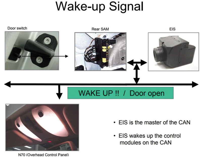
The EIS (Electronic Ignition Switch) and its control module (N73) actuates the driver-side SAM (N10/1) via the CAN bus.
The headlamp cleaning system of the same model is switched on by actuating the wipe/wash function with the combination switch (S4). The electronic ignition switch (EIS) control module (N73) receives a signal and actuates the driver-side SAM (N10/1) via the CAN bus. The SAM, in turn, signals the headlamp wipe/wash motor via an analog voltage signal through the fuse relay box. As long as the combination switch (S4) is actuated for a minimum of 400ms, the HCS pump relay (K40/2K5) energizes the headlamp washer pump (M5/2) and the wiper motors for the HCS. The other devices listed above work in a similar fashion with either the switches or other sensors that send a signal to the SAM via the CAN.
Exactly how does the SAM interpret the CAN bus signals?
We’ve already learned that data is sent one bit at a time through two complementary signals on the controller area network high (CANH) and controller area network low (CANL) bus wires. The CAN bus is a message-based protocol, designed originally for multiplex electrical wiring within motor vehicles. The CAN controller receives the transfer data from the microcomputer integrated into the control unit/device (also known as CAN Node). The CAN controller processes this data and relays it to the SAM. Also, the CAN controller receives data from the SAM, processes it, and relays it to the CAN Node. The SAM is a transmitter and receiver in one. In diagramming a CAN bus system engineers sometimes refer to it as a transceiver. It converts the data that the CAN controller supplies into electrical signals and sends this data over the data bus lines. Also, it receives data and converts it for the CAN controller.
One way to understand the SAM is to think of it in terms of the router of your home or office network. All your devices — network printers, phones, computers — communicate with each other via your router. If you hit print on your PC, the data is sent to your network printer via the wireless router (think the SAM unit). The SAM is one of the nodes on the CAN bus line that interprets these signals and sends them to the proper components. Although the SAM is much more than a router, this analogy should help give you an overall picture of its operation.
The CAN data transfer process consists the following stages: supplying data, sending data, receiving data, checking data, and accepting data:
- Supplying Data: The CAN Node provides data to the CAN controller for transfer.
- Sending Data: The CAN transceiver (SAM) receives data from the CAN controller, converts it into electrical signals, either analog or digital, and sends them back into the network.
- Receiving Data: All other CAN Nodes networked with the CAN data bus become receivers.
- Checking Data: The CAN Nodes check whether or not they require the data they have received for their functions.
- Accepting Data: If the received data is important, it is accepted and processed. If not, the received data is ignored.
Where is this SAM?
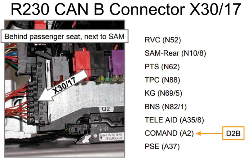
Based on the model and chassis you are working on, a SAM will most likely be found in or near fuse/relay panels. Mercedes-Benz cars may have rear and front SAMs. Most common configurations include two front SAMs, the left and right, and a rear SAM.
The left SAM, located in the engine compartment, typically handles left front lights, side light, a rear air outlet illumination, glove compartment lock illumination, light switch, the steering column adjustment motor group, ESP, SPS, and BAS control, AIRMATIC with ADS control unit, and the ABC control unit. The left SAM also receives signal data from the left front brake pad contact sensor, A/C pressure sensor, refrigerant temperature sensor, brake fluid indicator, outside temperature sensor, and the parking brake indicator switch. Low-beam headlights are most likely handled by the left SAM.
The right SAM is in the engine bay also. It’s responsible for the right front lights and the side light, center console storage, glove box, eyeglass compartment, ashtray, and foot well lights. It also handles pumping for the windshield washer and the Headlamp Cleaning System, radiator fan for coolant, the fan for the transmission oil cooler, and the circulation pump for the heating system delivery unit. It monitors the right front brake pad wear sensor, coolant and windshield washer fluid level indicators, the anti-theft alarm hood switch, and low-beam communication.
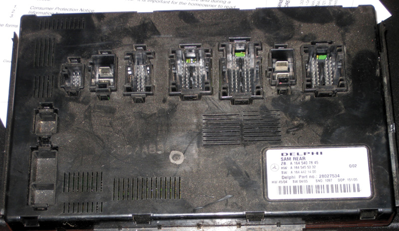
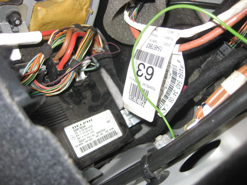
The rear SAM is typically under the right rear seat, or in the right-hand compartment in SUV models. It handles communication with the trailer recognition control unit, ESP, SPS, and BAS. It communicates with the overhead control panel, and controls rear lights, trunk closing, and “fasten seat belts†indications. Also, the fuel tank level sending unit and tilt sensor, the anti-theft alarm inclination sensor, door contact switches, and the rear brakes wear sensor.
Diagnosis and trouble shooting
Mercedes-Benz technicians will all agree on one thing: Diagnosing a faulty SAM unit is difficult and commonly time-consuming. Following a step-by-step test plan approach will help in determining faults in the whole network including a bad SAM.
As in most cases, a short test is in order to read out any fault codes. Conduct the test for the entire vehicle in order to get a total picture. Sometimes you may only be dealing with one customer concern (for example, “rear hatch inopâ€), however a fault code or communication error may turn up in another system that will give you some clues to solving the problem. If you find stored codes, then you can proceed with diagnosis based on them. But let’s say you have no communication with the front SAM unit, or any of the modules connected to it. Now, you must do some isolation work. Remember to start simple. What does a SAM or control unit need to communicate? Power, ground, and CAN bus wiring that’s intact. So, let’s start with power and ground. Does the SAM have both? Use your DMM (Digital Multi-Meter), and start with a voltage drop test to be sure you’re not losing voltage through a faulty relay or poor connection; however, this will not show you if the circuit is compromised because you are not seeing the load
on the system. We have always advocated performing the test between the battery + post and the load or Circuit 30 pin on the control unit. In TSB S-B-54.10/162, Mercedes-Benz advocates using the following method:
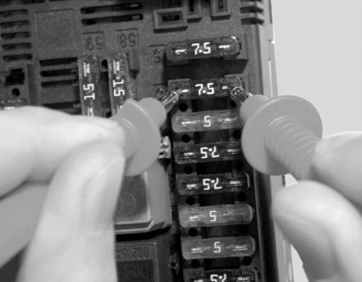
- Testing must be done on the installed fuse of the circuit 30 system (control module) using a suitable multimeter (e.g. Fluke 189) in the microvolt range.
- For an accurate measurement, use appropriately-sized pointed probes to ensure sufficient contact with the opening in the fuse’s plastic housing.
The quiescent current can be computed via Ohm’s law from the measured voltage value and the internal resistance of the fuse as measured. In some units, there is an internal fuse that can be serviced by opening up the case.
In many cases, you’ll want to check the software release of the SAM in question, and reflash if necessary. Another option that works sometimes is to perform a reset on the SAM (unplug the circuit 30 connector from the SAM and reconnect after 30 seconds).
How do you isolate the faulty unit?
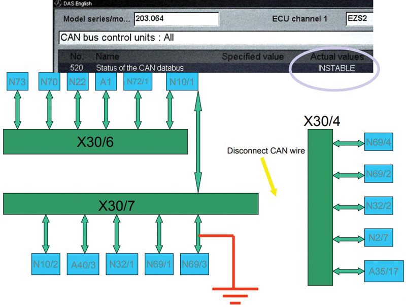
Here’s where XENTRY, StarDiagnosis, or a factory compatible scan tool is a prerequisite to going further in solving the problem. Let’s look at a scenario on a w203 with a shorted control unit:
First you’ll need to navigate to the proper data screen. Under EIS, look for the subheading Actual Values
- CAN bus control units
- Actual status CAN bus control units
- CAN bus control units: ALL
On your screen, if you have a shorted unit under actual values you will see INSTABLE. From here you will need to begin unplugging control units on the designated bus line.
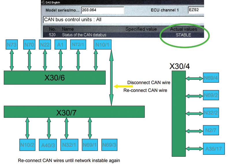
As you disconnect and reconnect the CAN wires, you will have isolated the control unit at fault when your actual values read Stable.
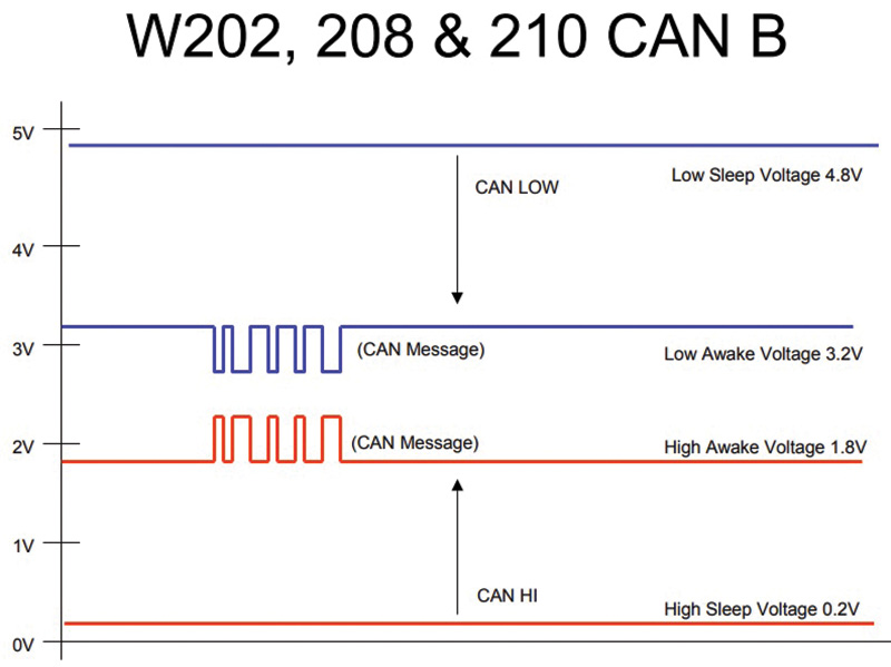
Now you have narrowed it down to two possibilities. Either a faulty control unit (SAM), or corrupted/shorted CAN bus wiring. Here’s where you need to break out your lab scope. At the N10/1 node (SAM), disconnect the CAN Bus connector and attach your scope.
Note that the SAMs are designated by the N10/ configuration. You should see proper high and low CAN voltages that will somewhat “mirror†each other.
If you have determined that your CAN bus wires are okay, then you can confidently replace the SAM unit that is suspect. Typically, CAN wires don’t just fail, but if they are compromised it is usually due to some chafing or crushing damage in a body cavity somewhere — rear hatch, door jamb, etc.
It is important to note here that many times when you have a bad SAM unit there is an underlying cause that must be addressed. According to the WIS manual, corrosion is the Number One cause of failure. Mercedes-Benz identifies control units as water resistant, but not water proof. Look for possible water intrusion. Likely places for rear SAMs are the tail lamp assemblies and hatch on ML and GL models, and door seals and body plugs on sedans. As far as front SAMs are concerned, look for a plugged front windscreen drain causing water to overflow into the engine compartment.
Coding
If you find it necessary to replace a SAM, the proper coding of the new unit will have to be performed. If possible, using a compatible scan tool read out the coding and fault coding of the old unit. Clear any fault codes. With some faulty SAMs this will not be possible. After you have installed the new SAM, follow the on-screen prompts to properly code the new unit to the vehicle. When done, you may be prompted to complete basic programming, which in the case of a front SAM will consist of things such as:
- Set time on cluster
- Switch low beam on and off
- Switch A/C on and off
- Normalize the power windows and sliding sunroof, if so equipped.
You may be saying “I do not like them SAM I am,†but these types of processors are here to stay. Starting with 2019 and 2020 models, the CAN systems will be able to handle even higher speeds and the SAMs will be even more sophisticated with the newer protocols. It will pay to invest in the training and equipment needed to service these ever more complex automobiles.





0 Comments