While preparing the New Beetle article for the October issue, I read as many VW and Audi service bulletins as I could find for additional information. One, while not uniquely related to the New Beetle or any other specific car, surprised me because it conflicted directly with everything I’ve heard about secure electrical connections: The gnarly electro-wizards of Wolfsburg say to use a crimped connection Instead of a soldered one to maximize the security and permanence of the connection!
VW Technical Bulletin, Group 97, Number 98-03, says “various electrical malfunctions could have been caused by improper repairs to the wiring harness (i.e., soldering, wire nuts, taping etc.).†OK, wire nuts and tape tangles are for putz-electricians, but soldering?! I thought that was the best possible electrical connection, much more secure than a crimp connector as long as you used rosin-core solder instead of acid-core (which is for plumbing and other mechanical, hydraulic or pneumatic joints rather than electrical connections). Could they be right? Their contention, in more detail, is this:
Soldered joints are of questionable quality and reliability.
The soldering process itself can damage other components from heat.
There is a ‘spark-gap’ condition at large gauge soldered wire connections, where the heat generated by the solder’s resistance could be enough to melt the insulation or set it aflame.
Wires tend to flex near soldered joints, increasing the chances of breakage and corrosion, particularly after heating. Heat causes wire embrittlement, strand fatigue and corrosion.
‘Technical inferiority’ of a soldered joint, where wires are ‘stuck’ together, while a crimped or welded joint is the equivalent of fusing the metal. With a soldered joint, there is only minimal contact between the wires themselves, and the main electrical path is through the solder (which has more resistance than the copper of the wire). Though crimping effectively reduces the crossection of a wire by about 20 percent, the small resistance added amounts to an essentially unimpeded electric flow across the crimped joint.â€
Hmm. The theory sounds plausible enough, but the opposite story seems just as likely a tale — more metal-to-metal surface connection with a soldered joint, the possibility of corrosion inside a crimped connector, loosening of a crimp with heat. Some of what they say is uncontroversial enough: using a electric soldering gun on an ungrounded, unprotect-ed computer circuit could induce a current/voltage spike in the system, but I was skeptical of the last part, so I rigged up a test. The arrangement was simple (as self-destructive ‘infernal machines’ generally are, I suppose). We used a large (1000 ‘cold-cranking’ amps) battery with a trickle-charger keeping it pumped up, a carbon-pile battery tester and a few heavy-gauge connections to our test wires. To simulate a reasonable tension on the wire, I used an el-cheapo ‘fisherman’s de-liar,’ a small, spring-loaded scale with a snag hook at one end and a finger-ring at the other. Naturally, we set a fire extinguisher at hand – as the only independent magazine I know of with our own shop, I wasn’t sure whether we could schmooze another if we burned this one down.
It’s unlikely the dimestore de-liar scale is very accurate, but I put about eight indicated pounds of tension on each wire tested, so the tension was probably about equal for each repetition. I didn’t use insulated crimp-connectors or shrink-tubing for the tests, although you would on any actual electrical connection. I left them off to see somewhat better what happened at the joint. Unless I miss my guess, the only difference the insulation would have made for our results would be more smoke and a bit quicker melt-through because of retained heat.
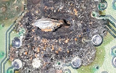
All we had to do then was to start twisting the car-bon-pile load button just as we started the shutter drive, and stop everything once the wire or connection made like a fuse, blasting pyrotechnic smoke through the insulation. As you can see, the smoke leaked out with some vigor: A few hundred amps make short work of a 14-gauge fusible link. Don’t try this at home — take my word for it, melted and burning insulation sears the lungs.
I assume the hottest part of the wire is the outside perimeter, since that carries the current. In any case, that’s where the hot copper meets the plastic. And I assume the inside of the insulation, tight-wrapped over the hot metal, boiled to liquid first and then to smoke, popping many pressure holes along the insulation jacket and blowing the combination of liquid plastic, smoke and finally liquefied and vaporized copper or solder out. The alert reader will notice how the slow-witted owner of the hand pulling on the fisherman’s de-liar, once burned and thus twice shy, togged himself out with a welder’s glove after the first unrewarding incident with spattered molten solder.
Our tests were nothing if not conclusive: In each case, the crimped connector held until the current melted the copper of the wire and broke the circuit open. In each contrasting case, the soldered connection melted before any of the copper wire burned. Looks like those Wolfsburg wizards did their homework on this one.
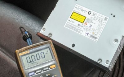
Why were the results this way? I’m guessing, of course, at this point, but not guessing blind. Copper will carry a great deal more current for its cross-sectional area than solder can, so unless the solder joint were much thicker than the wires it joins, it would probably have higher resistance. Solder’s melting point is also much lower than copper’s. I don’t know about the relative resistance of steel in the crimp com-pared to solder (both measure zip on the ohmmeter, of course, but that’s with no current load). But steel has a much higher melting temperature than either solder or copper, so when the crimp got very hot, it kept its grip as long as the copper wire held solid.
How realistic is this test? After all, most circuits have a fuse on them somewhere that pops the circuit long before you release the smoke from the wires. No doubt that’s right, but it’s not clear changing this would change the results of our tests. A lower temperature at the connection would certainly not count against the steel and for the solder; even at room temperature and under only mechanical tension, the crimp connector is stronger. Of course, you shouldn’t route electric wires under any tension at all, though somehow many of them end up that way. Again, lack of mechanical tension is not going to work in favor of the solder or against the steel sleeve.
Corrosion and electrolysis will occur, of course, whenever there are dissimilar metals in any sort of humid conditions, and there is more internal surface for the humidity to reach inside the crimp connector. Nonetheless, anecdotal observation points to soldered joints suffering more often than crimps from such loss of electrical and mechanical integrity. VW says that a soldered joint will also mean the increased risk of cracking at the wire on either side of the soldered joint, a risk somewhat greater than that for a crimped connector. We don’t have equipment to flex a connection a few thousand times back-and-forth, of course, but it is conceivable to me that the relatively sharp edged taper of the solder might make a sharper corner than the looser fit of the crimp. In any case, I haven’t seen many connections that broke because the wires flexed, not nearly as often as other kinds of electrical circuit failures.
Is the high current we sent through the connector a true test? Well, it does confirm that the steel-sleeve crimp connector will hold under higher current than the soldered one. And that seems to be the most secure test.


0 Comments