
What Georg Ohm saw, how to apply it, circuits and voltage drop
In the first part of this StarTuned feature, we covered electrical theory from the behavior of electrons through the way their movement and “pressure” are measured. This time, we’re going to apply that science with explanations of how to interpret Ohm’s Law, circuit types, voltage drop and some truly practical tips.
Voltage, amperage, and resistance are all related. One volt is the pressure or potential needed to push one ampere through a circuit with one ohm resistance.
The combination of voltage and amperage determine the power going through a circuit. The relationship among voltage, amperage, and resistance is described by “Ohm’s Law.†As long as you know the value for two of the terms, you can quickly calculate the third:
- To find the voltage of a circuit, multiply amps by ohms.
- To find ohms, divide volts by amps.
- To find amps, divide volts by ohms.
To be perfectly accurate from an historical standpoint, that’s not Ohm’s Law. What Ohm discovered was simply that the current through any piece of metal is directly proportional to the potential voltage difference across it. Double the voltage drop and twice as much current will flow. What we now call Ohm’s Law by common usage is the extrapolation of that discovery into an extremely useful set of formulas.
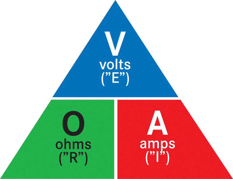
Ohm’s Law is usually illustrated as a circle or a triangle with voltage on top, ohms, and amps on the bottom, side by side. To find a missing value, cover the term you don’t know with your fingertip and then do the calculation based on what you see.
For example, if you don’t know the voltage, cover the V with your finger. Then multiply amps by ohms. If you want to measure the resistance in ohms, cover the O and then divide the voltage by the amps. Fortunately for most automotive work, V is constant. It is either the battery voltage reading with the engine off, or alternator voltage with it running.
Note: Most pictorial depictions of Ohm’s Law use Intensity (I) for amps, Electromotive force (E) for voltage, and Resistance (R) for ohms which can be confusing. The one included here uses the easily-understood terms, Volts, Amps, and Ohms, with the “official†terms shown below.
Play with the chart by making up numbers for two values to see what the third value will be. Do this a few times and you will see the following relationships:
- When ohms go down (resistance is low) the amps increase and voltage falls. In other words, with less resistance, it takes less potential (voltage) to move more amps.
- When ohms rise (corroded connection or higher resistance, perhaps) amps fall and voltage increases. It takes more potential (voltage) to move fewer amps when resistance is high.
- If voltage decreases, so will amperage if resistance stays the same.
Electron round-trip routes
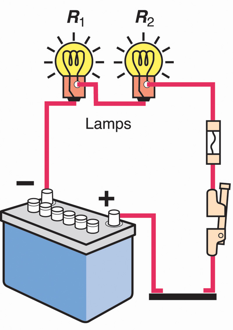
Automotive circuits are one of three types: series, parallel, and series-parallel. The series circuit is the simplest. The power source (usually the battery), the device or devices, the switches, and possibly a fuse, are connected by one wire. If there is any break in the circuit, everything quits.
A parallel circuit has more than one path for current flow. After leaving the power source, the wiring is split into two or more different paths.
In a series-parallel circuit, some components will be in series, others will be in parallel. If there’s a break in the series portion, everything goes out. If there is a break in one of the parallel sections, current will flow through the other parallel circuits.
Most automotive electrical problems are opens, shorts, and high resistance. An open is a break in the circuit. Without a continuous round-trip circuit, current flow stops. In a series circuit, everything is dead. In a parallel circuit, one branch will be dead, the other will work normally. Common causes of an “open†are a switch that has failed, a connection that has come apart, or, of course, a broken or cut wire. Sometimes, you’ll find a component that has failed internally and will no longer conduct electricity.
A short means the current is going directly to ground or the negative terminal without passing through any device. Shorts have little or no resistance, which allows maximum current flow with little voltage required. If there’s a fuse in the circuit, a short will blow the fuse to prevent damage. If a new fuse blows right away, you must find and correct the short.
High resistance means there is corrosion, a loose, but not broken connection, or some other problem that restricts current flow. A loose or corroded ground is one of the most common, but often overlooked, causes of high resistance in a circuit.

V drop
Although resistance is stated in ohms, for most automotive work the best way to test for high resistance is with voltage, specifically “voltage drop.†We’ll cover voltage drop in more detail in a future article on testing, but a brief description will explain why it’s a better test for resistance than reading ohms directly.
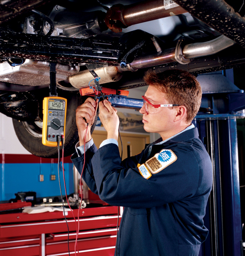
Voltage drop is measured “across†each component, with the positive lead on your voltmeter on one connection of the component or length of wire and the negative lead on the other. Make sure the negative lead is on the side that goes to ground.
When there is power in the circuit, you are measuring the “voltage drop†across the component. Any load in a circuit, good (an accessory or wiring) or bad (poor connection) absorbs voltage. The measurement is the amount of voltage absorbed.
Where you can get confused is that your meter connections are in parallel to what you are measuring (current is flowing through the component and through your meter at the same time, in a parallel circuit). What your meter reading shows is the DIFFERENCE between the available voltage on one side of the component and on the other. A high voltage drop reading means whatever you are measuring is absorbing a lot of voltage, leaving little for the rest of the circuit. A low voltage drop reading means that section of the circuit is absorbing very little voltage.
Switches, wiring, and other connections should have very little voltage drop because they are not supposed to absorb much voltage. If the reading is high, something is wrong — there is too much resistance. Devices, such as a light bulb, blower motor, etc., should absorb voltage. If there is only one device in a 12 volt circuit, the device should absorb all 12 volts, except for the small amount that may be lost in the wiring. If there are two devices, both the same size, each will absorb 6 volts. The specific math and test procedures will be covered in a future article.
Why use “voltage drop†instead of measuring ohms? Because measuring ohms requires the circuit to be turned off. Each component or device is measured separately, which isn’t how a circuit operates. Measuring voltage drop tells you what is actually happening when the circuit is powered.
Practical points

Integrating the following practical, if random, points into the overview you’ve just read should bolster your understanding:
- The last ditch procedure of jumping a fuse with a wire or a sawed off bolt to find a short has burned lots of cars to the ground. Use a relay type short finder.
- Three important things to remember on any troubleshooting job, electrical or electronic: grounds, grounds, grounds. Is there corrosion under that screw? Has a strap or cable been left off?
- Wires shouldn’t get hot. You’ve got a problem.
- Ampacity is the safe carrying capacity of a wire in amperes. Doubling the amperes without increasing the wire diameter increases heat four times. The potential energy that each electron loses by traveling through the voltage drop is left in the conductor in the form of heat.
- There can be a big difference between hot resistance and cold resistance. In metal conductors, resistance rises with temperature, so a lamp you measured at one ohm may have many times that when the filament is glowing. If you had used one ohm in your calculations, the amperage reading you actually got wouldn’t coincide with the formulas.
- On the other hand, the resistance of nonmetallic conductors such as carbon falls as temperature rises. That’s useful for thermistors, among other things.
- You can get into trouble with your sophisticated DMM (digital multimeter) because of its 10 megohm (that is, 10 million ohms) input resistance or impedance. In a lighting circuit, for example, you may find 12 volts, but there might be 20,000 ohms in the socket. If you were to use a test light, it wouldn’t glow.
- You’ve heard of “brown outs” in commercial electric grids? Well, the same thing happens with DC. At 90% of rated voltage, a motor produces only 81% of its normal power output, a lamp a mere 70% of its candlepower.
- The thicker the wire, the smaller its gauge number.
- Multi strand wire can carry more current for the same diameter than solid, single strand wire. It’s also much better at surviving the stress of flexing.
- Although it may seem like a good idea, don’t use ordinary RTV silicone to coat or insulate splices. The acetic acid solvent eats copper wire.
- A typical DMM measures resistance by passing a known current through the circuit or component, gauging the voltage drop, then calculating the ohms present using Ohm’s Law: ohms equal volts divided by amperes.
- Voltage is always looking for an easy way out.


0 Comments