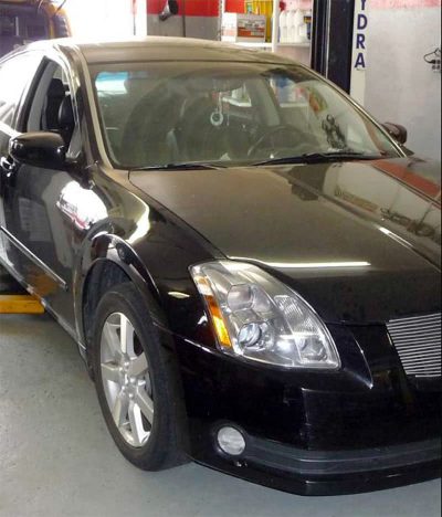
I was called to a shop to perform an immobilizer key programming on a 2005 Nissan Maxima (Figure 1). The vehicle was towed in with a flashing security light on the dash and the shop did not have the proper equipment to perform this task. Security systems are usually not supported by aftermarket scan tools, so require the use of a factory scan tool to perform this task. Some manufacturers use security pin codes that must be input into the factory tool before you can start the procedure. These pin codes can sometimes be retrieved by the owner of the vehicle if he or she visits a dealer with proof of ownership. The other option is for techs to go through a series of steps with NASTF at www.nastf.org to register themselves to obtain a locksmith identification number, thus allowing them to visit any manufacturer’s website and purchase a pin number for the specific vehicle they are working on.
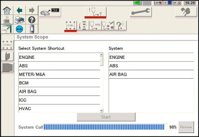
When I arrived at the shop, I attempted to start the vehicle to verify the complaint. The car did not start and had a flashing security light. I was told that the customer was driving the vehicle when suddenly the instrument panel and center dashboard displays started to function erratically and then they both stopped functioning. The customer pulled the vehicle off the road and shut it down, but when he tried to start it again, it wouldn’t.At this point, I decided to hook up my Nissan Consult III to get started. As the scan tool was doing a roll call to see what modules were present, only the Engine, ABS and SRS systems were identified (Figure 2). I quickly turned to the tech and said, “Dude, you got more than a simple key programming issue going on here!†This was very unusual because there were at least seven+ controllers on board this vehicle, and the one responsible for anti-theft was the BCM, and it was not on the call list. That would explain the security light flashing.
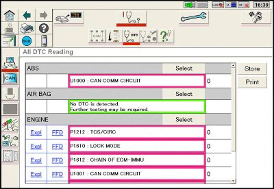
I next selected the DTC screen to retrieve codes from all present controllers at once to see what codes were stored in memory (Figure 3). The SRS module did not have any codes stored, but the ECM and ABS modules both had “U†codes stored in memory. When a controller stores a “U†code, it does not mean that there is a problem within that controller. A “U†code is a finger-pointing code directing you out into the network to find the problem controller. Some “U†codes may even be specific to which controller is at fault. I now knew I was dealing with a CAN network problem.
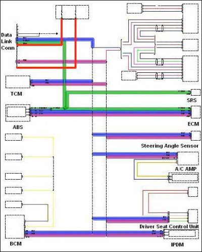
I next pulled up a diagram from Mitchell-On-Demand that provided an excellent representation of the computer data lines (Figure 4). I selected the most common controllers on the communication network and highlighted the CAN high lines blue, CAN low lines purple, and the Diagnostic K lines green. By studying the diagram, you can see that the reason I was able to talk to only the ECM, ABS and SRS systems was because they were all on a separate Diagnostic K line network. The SRS module did not set any “Uâ€codes because it was not tied to the CAN network like the ECM and ABS. The BCM, TCM and other controllers were on a CAN network.
I started to use some logical thinking about this situation without getting too high-tech. Sometimes when we approach things in a low-tech mode we can get to the root of problems quicker. Just like the saying goes, “Keep it Simple Stupid.†It was hard for me to believe that the BCM, TCM, Integrated Power Distribution Module and the Auto Drive Position controllers were all bad, or shared an open common power and ground feed. It would probably be more common for them to have an open or shorted network due to a harness failure or a bad or inoperative controller taking the CAN network down. I have seen something as simple as a blown fuse in the back of an Audi radio that caused the inoperative radio to feed back on the network resulting in a no-communication problem until the fuse was replaced.
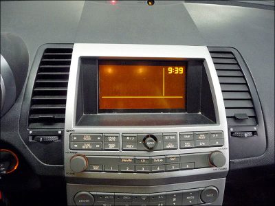
The easiest starting place for accessibility seemed to be the center dash (Figure 5). The center display panel was blank and the A/C control panel was inoperative, so it was just a matter of going right to the back of the panels to perform a power and ground check. If this did not pan out, then it would become a task of removing each controller from the network one at a time until the CAN network came back to life. The last option was to perform some serious labor in checking all the CAN lines at each controller all the way back to the diagnostic connector for a short or open circuit.
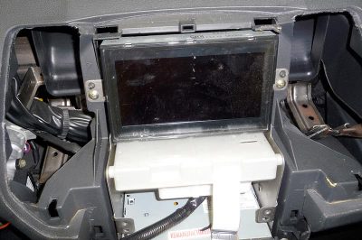
Pulling the center dash apart exposed the power supply module for the instrument cluster and A/C control unit. At the same time this power supply module was exposed, the tech and I saw coins fall to the floor that had been trapped between the screen bezel and the top of the power supply module. As we pulled the power supply module out to perform power and ground checks, there was a smell that I recognized immediately. It was a burning smell coming from the power supply module. As I handled this module, I heard rattling inside as if something had broken loose.
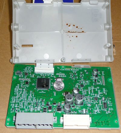
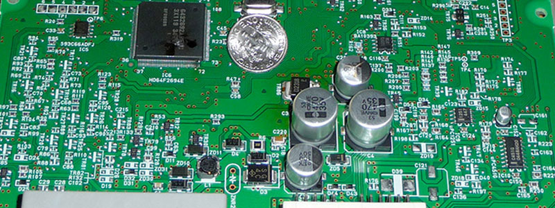
We opened up the power supply module to find a big surprise (Figure 6). There was a dime that worked its way into the module through a small slot on top of the housing. It bridged the circuit board and blew a capacitor. This you can see by the brown residue on the case cover (Figure 7). I can only imagine this vehicle as an automotive slot machine. What are the chances of change stored on top of the conveniently-located shelf of the center dash working its way down on top of the power supply module, then, from some sudden acceleration, deceleration, and right and left turns, the lucky coin of just the right size denomination makes it into the one exposed slot on top of the power supply module, thus taking an entire vehicle down? This driver deserves a prize!
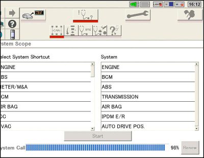
Going back to the vehicle I now noticed that the security light was no longer flashing so I went ahead and tried to start the vehicle and it started right up. I was on a natural high here giving all the guys in the shop a tech hug. It was one of the most amazing things I have come across in my field of diagnostics. At this point, I decided to recheck the vehicle with the Consult III and there were now seven controllers present (Figure 8). This power supply unit was internally damaged and took down the entire network so that none of the controllers on the CAN network could talk to one another, or to controllers on the K line network. This resulted in the ECM not receiving the immobilizor command from the BCM, which resulted in a no-start situation.
Having the proper equipment to diagnose a vehicle is only half the battle. You still need to use your five-sense diagnostics and some logical thinking. This requires keen sight, smell, feel and hearing, but I just don’t recommend the tasting part. The fact that I saw a blank panel and inoperative A/C controls attracted my attention to the center of the dash. That distinct electrical burning smell drew my attention even closer to the power supply unit and the internal rattle noise sealed the deal on the power supply module being a prime suspect in this diagnostic case. I hope you enjoyed this article and that it will shine some light for you if you encounter a similar dilemma in your shop.
by John Anello

0 Comments