
Most people think of diesels as loud, smelly, and underpowered. Not anymore. Volkswagen has been refining and re-engineering Rudolf Diesel’s ingenious invention for almost half a century. Let’s keep them running great for another 50 years.
Volkswagen introduced its first diesel into the United States way back in 1978. Many of those early versions are still in use today, kept alive by enthusiasts who appreciate their reliability, fuel economy and driving performance. They are obviously a wise automotive choice in today’s current economic and environmental conditions.
Volkswagen started to do major upgrades on its diesel engines for the 1993 model year with the introduction of the AAZ 1.9L turbo. Additional engines were developed, such as the 1Z turbo in 1996, and the AHU and AHH in ’97. The 1999 model year brought us the ALH motor that stayed in service until 2004. All of these are 1.9L turbos.
In 2004, the more highly-evolved BEW, BRM, and BKW engines were introduced, and in 2005 the BHW was released. These engines are all turbocharged 1.9L fours — except the BKW, which is the 5.0L 10-cylinder diesel offered in the Touareg.    In 2006, the BKW motor was improved and renamed the BWF. Finally, in 2008 the latest 5.0L V10 motor was dubbed the CBWA.
With proper maintenance, a Volkswagen diesel engine can easily exceed 250,000 miles in it’s lifetime. The higher the mileage, the more maintenance and repairs these engines will need. You should be able to keep them running well with proper care and access to the factory diagnostic procedures. We will focus on the popular ALH engine here, but most of this information can be applied to other Volkswagen diesel systems as well.

Fuel Supply

Part of the success of Volkswagen’s diesel systems is simplicity. There is no fuel pump inside or outside of the fuel tank. Look under the passenger side of the rear seat and you can remove the inspection cover. There is a filter screen, pick-up tube, and sending unit inside the tank. The fuel lines lead directly to the fuel filter, which is mounted under the hood by the passenger side inner fender. There is a bleed screw on the top of the filter to either fill with diesel fuel, or bleed out air in the system. Although Volkswagen recommends that the filter should be replaced every 20,000 miles under normal service, many service experts in the field suggest that you replace it at least once a year. Most of your customers drive these vehicles under severe service conditions. This means a lot of stop-and-go, and excessive idling. In addition, diesel fuel blends are changing all the time with new government regulations. Additives used to lubricate internal components can build up and solidify in the filter with every drive cycle, possibly slowing fuel flow. An OEM fuel filter provides the necessary quality to protect the diesel injector pump and the most resistance to clogging.
How does fuel get from the tank to the engine? The diesel injector pump has a rotary vane-type suction pump built into it that draws in fuel from the filter. This is why it is so important to have an unclogged filter. The vacuum generated should be enough to pull fuel from the tank without any assistance. If you are worried about a clogged supply line, you can run your own line to the pump from a can of clean diesel fuel. You are bypassing the screen in the tank and the fuel filter, so make sure the fluid is free of debris. Another way to test the pump is to put a vacuum gauge on the fuel inlet port and see how many in. Hg are generated while trying to start the engine. You should see over 10 in. Hg while cranking. This test lets you know the pump is strong enough to provide a steady supply of fuel for the pressure side of the pump.
First Things First

Before the fuel can get to the pressure side of the pump, it must first pass through the fuel cut-off valve. This solenoid is mounted toward the back of the injection pump, underneath the fuel return line. It has a single wire bolted to the top of it. This wire provides battery voltage to the solenoid, which opens the valve to allow fuel to flow. The power comes from the Diesel Direct Fuel Injection (DFI) module, a.k.a. the Powertrain Control Module (PCM) as long as conditions are correct. With the ignition key on, the solenoid should be energized. The engine does not need to be cranking or running. If it is not being energized, you need to check the power and ground supplies to the PCM.
Another input that can stop the PCM from activating the solenoid is the anti-theft system. If this does not like the transponder signal from the key, it will signal the PCM to “not†open the valve. You will have to look at data in the instrument cluster to determine if the anti-theft system is blocking the engine from starting. With a factory scan tool, you can perform an anti-theft system key alignment. This can be handled through any Volkswagen dealer’s tool rental and Immobilizer Information program.
Things Are Going Well
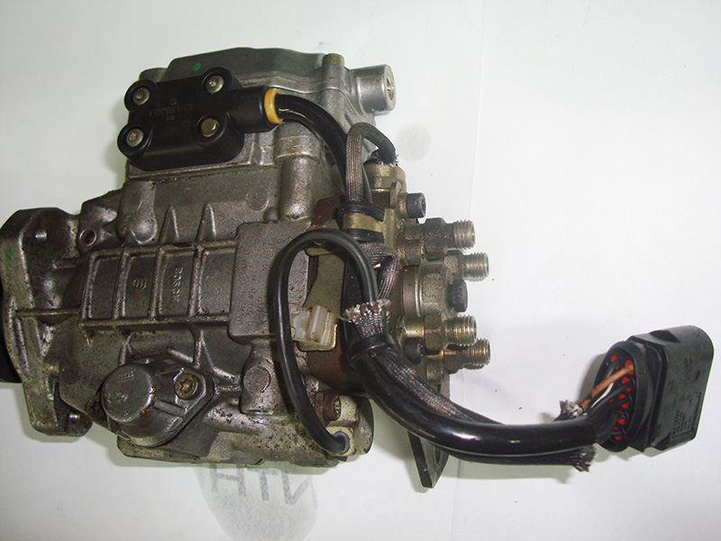
If the fuel supply system is functioning properly and the fuel-cut solenoid is letting fuel into the high-pressure injector pump, it can now start running, right? Wrong. There are several components of the injector pump that need to work together. The drive pulley spins a shaft in the injector pump. As this shaft rotates, it creates high pressure. As this pressure passes the injector ports, the fuel is directed to the correct injector in the firing order. As well as base timing, the TDI    Electronic Control Unit (ECU) can control injection timing to a small degree. It is also in total control of how much fuel will be delivered. These two readings are known as “Start of Injection Timing†and “Fuel Quantity†on your scan tool. Before you look here, you should check some basics.
Setting up base timing is, of course, critical to getting the engine started. This is performed with some special tools to lock down the camshaft and injection pump while the engine is positioned at TDC. This procedure will need to be performed if any of the timing belt components are replaced. First, you will need to turn the crankshaft to TDC. The mark to indicate TDC is in the oblong opening in the transmission bellhousing. Look for the “0†mark and line it up with the bottom edge of the opening. Now that the crankshaft is at TDC, you may as well line up the camshaft. Insert special tool VW #T10098 into the back of the camshaft with the valve cover off. You may have to remove a vacuum pump, if fitted.
Now that you have the crank and cam lined up, you can work on the injection pump. One of the slots in the pump gear has an opening that passes through the pump flange. Rotate the drive gear until this opening is at the 12 o’clock position. Then, insert special tool VW #3359 to lock the injection pump at TDC. You can now complete the timing belt installation. This level of timing will allow you to start the vehicle, but you may not have optimal performance. You may need to adjust the start-of-injection timing while the engine is running to get the best performance possible.
For this step, you must have a VAG5052, or equivalent, and monitor a few specific measuring value blocks. Injection timing is affected by several inputs. You must know these input values so that you can calculate what range the injection timing should be in. Look at measuring value block 000 and you will see 10 fields displaying information. The start-of-injection reading is in field #2. You will also need to watch coolant temperature. This reading is found in display field #7. Finally, you have to watch fuel temperature, which is found in display field #9. You need to watch all these inputs while the engine is running. Compare the inputs to the start-of-injection chart and see if the timing is within the proper range. If not, some adjustment is necessary.
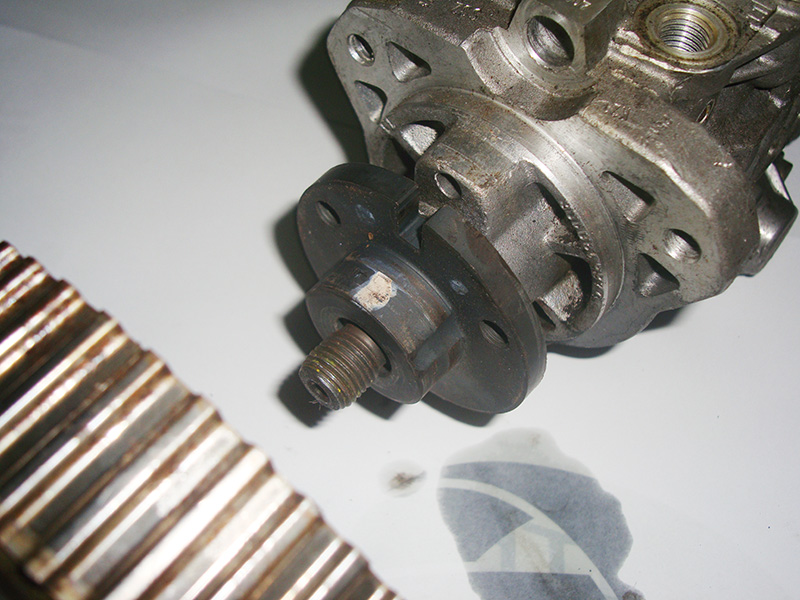
You must shut off the engine to make the adjustment. On the pulley of the injection pump, you will see a 22mm center bolt surrounded by three bolts that attach the pulley. The bolt holes are slotted, so there is some adjustment available when the bolts are loose. You can rotate the 22mm bolt that is threaded into the injection pump shaft, which changes the timing. Rotate the shaft counterclockwise to retard the timing and clockwise to advance. The gear will be held in place by the timing belt. Tighten the pulley bolts and restart the engine. Look at field #2 and see if you are between the upper and lower limits on the chart. If you are, no further adjustment is needed.
The computer detects the start-of-injection timing from the crankshaft and camshaft position sensors. The cam sensor is mounted in the #3 injector. When fuel is sent to the injector, an electrical pulse is sent to the PCM. You should make only very small adjustments at the pulley because small adjustments will result in large changes in start-of-injection timing. Also, an important point to remember is that the readings in fields #7 and #9 are not direct temperature readings. So, a reading of 75 is not 75 deg. C. For instance, a reading of 73 in field #7 means the engine coolant temperature is 85 deg. C. The fuel temperature reading should be between 50 and 210 in field #9 to perform this test. If is not within this range, you will have to either let the engine warm up or cool off.
The Computer Takes Over
How is the injection timing controlled? Inside the injection pump, a cam plate is mounted around the fuel distribution shaft. This is held in position by both spring and fuel pressure. An injection timing piston uses fuel psi to move the cam plate into the base or advanced position. The amount of advance can be up to five degrees. A component known as the “Cold Start Injector†controls how much fuel pressure is applied to either side of the injection timing piston. The PCM controls the cold start injector, either opening or closing it depending on rpm, temperature, load, etc. It only controls injection timing below 2,200 rpm. You can monitor the amount of advance with your VAD 5051/2/4 in either measured value block 004 or 005 for the ALH motor. Controlling the advance properly reduces HC emissions and noise, and increases fuel economy.
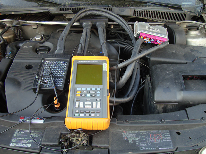
The second computer control has a bigger impact on fuel delivery. The PCM controls a “Quantity Adjuster†to increase or reduce the fuel delivered to the engine. This device moves a metering sleeve between the primary plunger and a spill port. If the metering sleeve blocks off the spill port passage, maximum fuel pressure is achieved. If the sleeve is commanded to open, all fuel pressure is directed to the spill port resulting in no pressure at the injectors. The adjuster can vary the pressure anywhere in between, and its position is monitored by a sensor in the injector pump itself. An AC pulse generated wave is sent to two resistor boards. The adjuster rotates on one board and the other remains fixed. One AC voltage remains steady and the other increases when the adjuster changes position. You can watch this signal with a lab scope, but looking at scan tool data will probably be a better indicator of the quantity adjuster position.
In Conclusion
As highly-evolved as it is, a Volkswagen diesel injector pump is still basically a pump. If any drivability problems arise, the base timing must be checked. Beyond that, the computer controls that advance injection timing and increase and decrease the injection pulse must be investigated since they can have a significant effect on drivability. Knowing how they function is half the battle.
Download PDF


0 Comments