Luxury is more than just Automatic Climate Control. Nowadays, sensors respond to sunlight, humidity, and even air quality. Let’s review how these systems function to keep the passengers in the habitable zone.
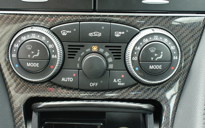
Here we have an AAC module. You can access self-diagnostics with your SDS scan tool. This unit directly controls blend flap (mode door) operation, but signals SAM modules to control other outputs such as that to the compressor.
When we think of luxury, we think of velvet smooth power delivery, compliant suspension, and all the passenger-compartment creature comforts. Where the last is concerned, nothing exceeds a Mercedes-Benz vehicle. Whether it is a manual or automatic climate-control system Mercedes-Benz offers a wide variety of operating modes to best cater to the desires of the passengers. Dual and multiple zones allow separate temperatures and modes to be selected.
While manual systems set a general temperature range, they are still electronically controlled, and most have self-diagnostic capabilities. Automatic systems allow you to set a specific temperature, then they monitor changing conditions and make adjustments to temperature and mode door operation. New sensors have been added to enhance performance. While these systems are more sophisticated than they once were, they can also be more time-consuming when it comes to diagnosing a problem.
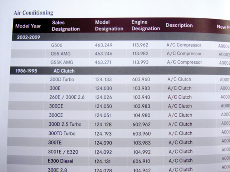
Mercedes-Benz has an extensive remanufactured parts program that includes A/C compressors and clutches. This may offer a cost savings for your customers along with OEM quality.
While manual systems set a general temperature range, they are still electronically controlled, and most have self-diagnostic capabilities. Automatic systems allow you to set a specific temperature, then they monitor changing conditions and make adjustments to temperature and operation flap (more commonly called “blend door†or “mode doorâ€) operation. New sensors have been added to enhance performance. While these systems are more sophisticated than they once were, they can also be more time-consuming when it comes to diagnosing a problem.
At the introduction of the ML320 (163 chassis) in 1998, the HVAC system did not have self-diagnostic capabilities, and through 2001 the service literature never refers to this as AAC. The system has two main parts. There is an A/C/Heater switch in the dash that has three round dials (look in the wiring diagram at component S98) that indicate the selected temperature, mode flap position, and blower motor speed to the second, separate part, the A/C pushbutton control unit. This unit is mounted behind the A/C/Heater switch in the dash panel (in the wiring diagram, component N19). It (N19) directly controls the temperature blend flap, and monitors evaporator and interior temperature sensors. If either of these temperature sensors fail, or indicate too-cold temperatures, the compressor will not be commanded on by the module.
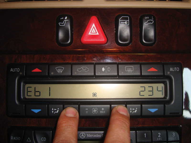
Up to 2002, E-Class vehicles have self-diagnostics built into the control unit. You can access DTCs and clear them. Refer to www.startekinfo.com for code definitions and testing procedures.
A separate All Activity Module (AAM) is located in the under-hood fuse/relay panel. This controls the relays that supply power to the blower motor, auxiliary coolant fans, coolant circulation pump, and compressor. A conventional resistor board drops the voltage for various fan speeds. The AAM is on the CAN, so you can use your SDS software to see if the compressor or cooling fans are commanded on. You can also quickly see the refrigerant pressure sensor reading to determine if there is a proper charge in the system.
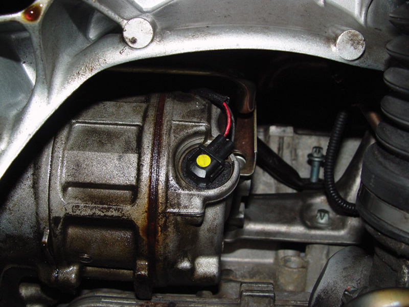
Variable displacement compressors do not have clutches. They use a rubber coupling that disengages if the compressor seizes. A compressor control valve changes the output of the compressor depending on the requirements of the AAC or C-AAC control units.
In 2002 CAN, additional temperature sensors and computer-controlled mode doors were added to better control cabin temperature, and the Automatic Air Conditioning (AAC) module was introduced. These new sensors are inputs directly into the AAC control unit. An outside temperature sensor is used to calculate compressor operation. If one were to get damaged or ripped off in an accident, an open circuit would suspend compressor operation. The AAC module signals the front SAM to operate the compressor, but not through clutch control. Instead of the traditional fixed-output compressor and electro-magnetic clutch, a variable-displacement compressor is used. Here, the compressor is always spinning (a rubber coupling in the pulley disengages if the unit should seize), but a swash plate inside can be commanded to minimum stroke resulting in little to no output, and vastly reduced parasitic drag.
An A/C Compressor Control Valve determines the position of the swash plate. The AAC tells the SAM module where it wants to position the compressor swash plate, and therefore its output. This AAC unit controls all electric mode doors through its own CAN system referred to as CAN-KLA, and blower speed is now controlled with a module instead of resistors. A rear air conditioning system was also added, but it only has mode and fan speed control. Self-diagnostics also became available to quickly and accurately address problems. The compressor and cooling fans are now controlled by the SAM.
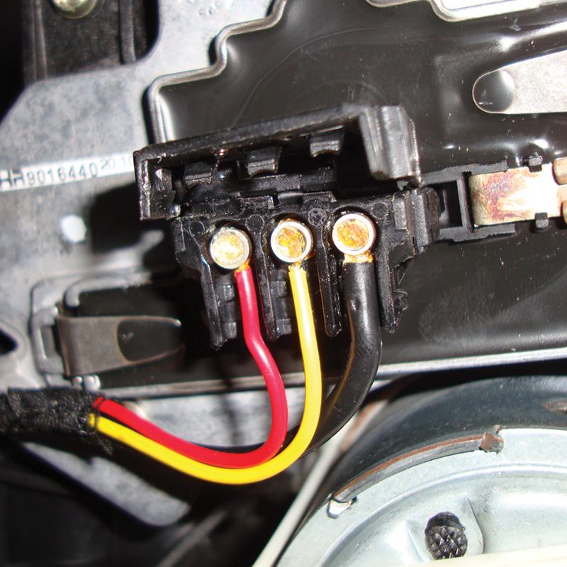
There are three pins on the blower module. The red and black are power and ground, respectively. The yellow wire carries the blower command. On this 210 chassis, you should see one volt for low speed, and 6.5 volts for high speed.
Now that AAC units are on the CAN, you can use SDS, available for purchase from MBUSA, to interrogate the control unit and quickly look for DTCs, observe live data, and command specific outputs to test if they are working properly. This can reduce your diagnostic time and lead to a more accurate repair. However, on 210 chassis up to 2002, dual zone automatic climate controlled systems can display DTCs right through the AAC control panel.
Codes can be pulled by setting the driver’s side temperature to “HI†and the passenger’s side to “LOâ€. Within 20 seconds, press the “REST†and “EC†buttons together. The display should go blank and you will notice the “recirculation†LED flashing and the letters “diA†will appear in the display. By pushing the passenger’s side “Auto†button you can advance through each code. You must display all codes before you can erase them. Hold both “Auto†buttons down until the letter “d†is displayed on the driver’s side of the screen, and “FF†is displayed on the passenger’s side. The codes are now cleared.
Other chassis, such as the 215 CL Class in 2000, use only the DAS software to communicate with the two-zone Automatic Air Conditioning (AAC) Thermatic, or four-zone Convenience Automatic Air Conditioning (C-AAC) Thermotronic systems. Manual systems are two-zone, and do not have an LCD display screen as part of the AAC control panel/unit. The manual two-zone systems have a single dust filter, which should be replaced every two years or 30,000 miles, so make a habit of asking your customers when it was last changed. Four-zone systems use two activated-charcoal filters. If the system detects a failure, and shuts off the compressor, the LED in the “EC†or “A/C Off†pushbutton will blink. Variable displacement compressors are used and are still directly controlled by a SAM. This is usually one of thefront SAMs, but on two-door models such as the 230 chassis it may be the Driver’s-side SAM.
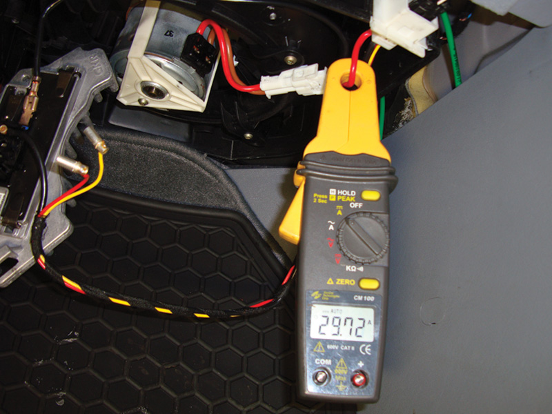
You should always check the amperage draw of the blower motor when replacing the blower module. Excessive amp draw can damage the new unit. Blower motors typically draw about 30 amps during high-speed operation.
Transistorized blower modules allow for multiple fan speeds without additional resistors. These modules can either supply variable positive voltage or ground, so check the wiring diagram first. An analog voltage signal from the AAC control unit is used to command additional voltage or ground to the blower motor. The module also requires its own power and ground supply. On the 210 chassis, the voltage that controls fan speed is almost one volt for low-speed operation, and can go up to 6.5 volts to command high speed. The blower motor itself normally draws about 30 amps at maximum speed. If the amp draw is too high, the module may burn out, so check it.
Aftermarket replacement parts do not necessarily have quality circuitry, so it is not unusual for these parts not to last. Mercedes-Benz offers remanufactured A/C clutches and compressors that meet O.E. standards, so be sure to check with your Mercedes-Benz parts supplier before you’re tempted to use something of dubious quality that may end up damaging your reputation. Â


0 Comments