Â
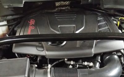
I was called in to a shop for a MIL-on (Malfunction Indicator Lamp, a.k.a. “CEL” for “Check Engine Light”) situation in a 2000 Toyota Solara with the 1MZ-FE engine (Figure 1). The shop had replaced two air/fuel ratio sensors, but the MIL came back on after the vehicle was delivered to and driven by the customer. The tech had checked all the fuses, but could not locate the source of the circuit problem affecting the sensors so he wanted a second opinion to get this monkey off his back and down the road. It was bad enough that the shop had replaced parts that were not needed, but now the customer was putting pressure on the shop to get the car fixed, or he wanted his money back. We’ve all been down this road and it’s not a good feeling because you know whatever turns up is going to have to be fixed at your expense and chalked up to the never-ending automotive learning curve.
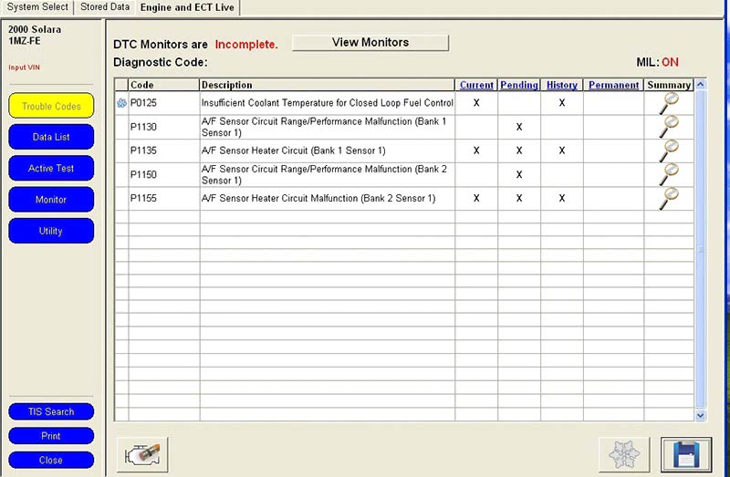
When I arrived at the shop, I noticed that the MIL was on so I opted to hook up my Toyota Techstream scan tool to see what codes were stored in the PCM. I selected “Trouble Codes” from the menu and found five codes stored in memory (Figure 2). Two of the codes, P1130 and P1150, were related to a range/performance issue with both upstream air/fuel ratio sensors. The next two codes, P1135 and P1155, were related to a heater circuit malfunction in both of those sensors. The fifth code P0125 (Insufficient Coolant Temperature for Closed Loop Fuel Operation) is one that takes many scan tool gurus down the wrong diagnostic path. They often mistake this as an indication of a bad engine thermostat when in reality it is letting you know that the air/fuel ratio sensor can’t reach its proper operating temperature due to a heater circuit problem.
Looking at the main four air/fuel ratio sensor codes, you need to divert your attention to heater circuit faults because if one is present range/performance codes will always be set as a secondary fault. If you think about it for a moment, you’ll realze that it’s not very likely that two A/F sensors would go bad at the same time, or even two heater driver circuits. It’s much more likely that something common to both heater circuits is at fault, such as a power feed source. Streamlining diagnostics like this cuts your chances of taking the wrong diagnostic path, so it’s important to use some “street smarts” when you approach a problem. It becomes a matter of automotive forensics to sift through the information you’ve gathered from your tests to see what’s really pertinent to the problem, then to apply logic.
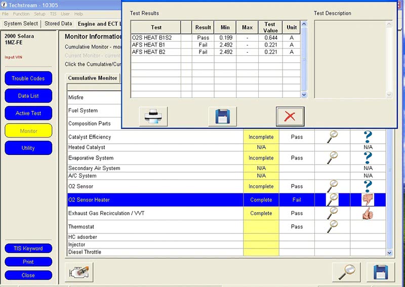
Mode 6 is a scan tool feature that isn’t used by techs in the field nearly as often as it should be. This is mostly due to the unfriendly user interface that most scan tools, including factory units, provide. Toyota, however, has done a phenomenal job making things easier through hyperlinking. You go to the “Monitor†selection menu and there you will view all the monitors with their pass or fail status (Figure 3). Notice how the thumbs-down sign for O2 heater failure instantly draws your attention with a universal language. Click on the thumb and it will hyperlink to Mode 6 test results that are easy to read (Figure 4). By looking at these readings you can see that both upstream A/F sensor heaters failed to achieve the minimum current threshold of 2.492 amps — their test value was at 0.221 amps. By viewing the threshold information, you can conclude that both heater circuits pulled almost no current, which is an indication of an open circuit for both banks.
Â
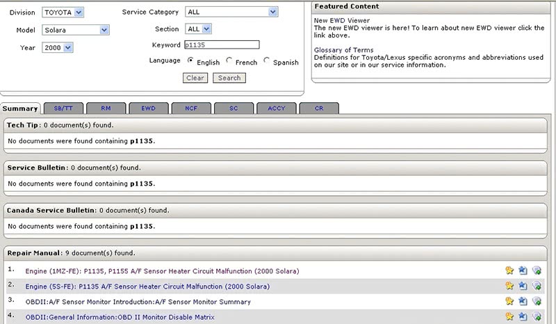
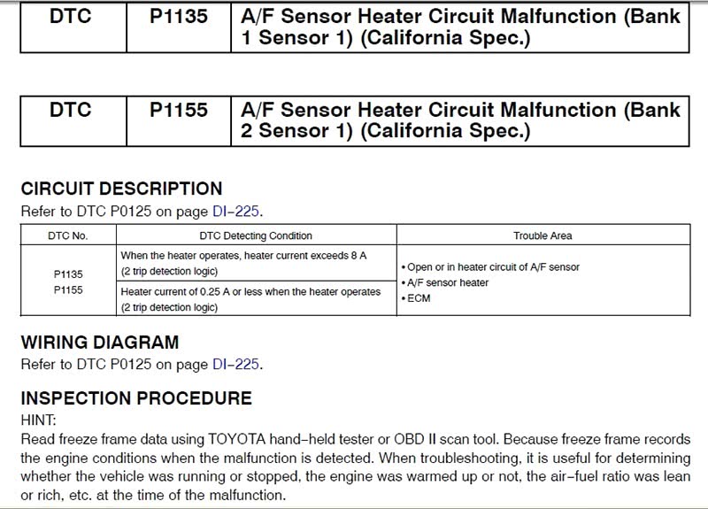
This scan tool is hooked up live to the Toyota website through a subscription, so all I needed to do is use the “TIS Keyword” menu selection, which took me directly to Toyota’s website search engine. By placing the heater code P1135 in the keyword window, I was able to do a full search of the Toyota website and be directed to linked information to help me further my diagnostics (Figure 5). I clicked on the Repair Manual link for the code and it hyperlinked me to all the information I needed to perform my diagnostic tasks (Figure 6). You’ll notice the simplified layout of the DTC description, followed by circuit description, wiring diagram, and inspection procedure. The information on this page listed the code as two-trip detection logic and provided a maximum 8.0-amp or minimum 0.25-amp threshold for code setting.
Â
Â
Â
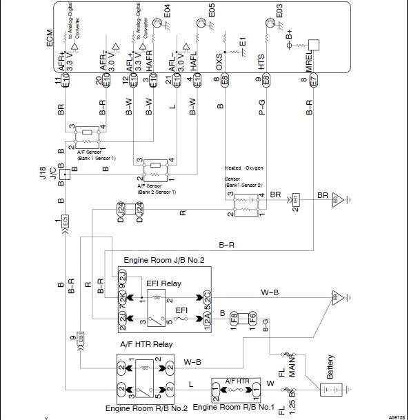
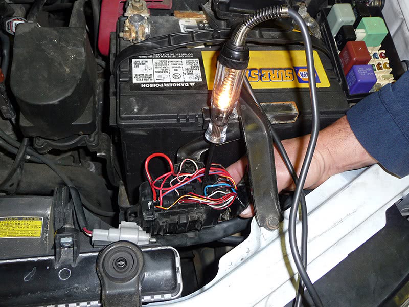
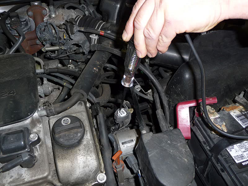
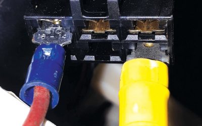
I used the hyperlink DI-225 under “Wiring Diagram” and was linked to an isolated diagram of the heater circuit (Figure 7). By power-flow checking the diagram, you can see that power feed to the heating elements is supplied through the A/F heater relay contacts from an A/F heater fuse. I located the relay in the engine compartment relay box #2 and turned the box over to backprobe the relay contacts (Figure 8). The test light lit with the key on indicating that power was being supplied to wires leading to the sensors’ heaters. I next unplugged the Bank #2 A/F sensor connector located at the back of the engine to test it for power and found nothing there (Figure 9). There was an open circuit between the relay panel and the A/F sensor connector.
When looking for an open circuit, you need to find out where the circuit begins and where it ends. Then, try to visualize how the circuit is routed — it’s almost like using X-ray vision. Next, find an accessible midpoint. This location will help you to determine if the problem is forward or backward of the area you have chosen. Start homing in on the open by tapping into the circuit with a test light to validate power feed. The midpoint I chose on this vehicle was the battery tray because the harness ran under the battery, then towards the rear of the engine where it was supposed to feed the bank #2’s A/F sensor connector.
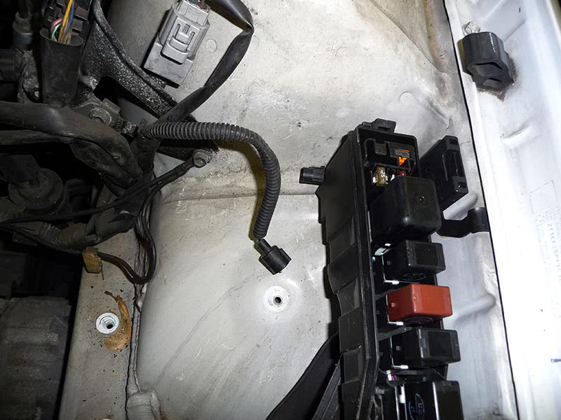
When I removed the battery and battery tray, I immediately noticed a crushed black wire housed in a conduit that was unplugged. It seemed to fit the description of a black wire that fed thesensor’s heater circuit. I decided to plug it back into a mating connector located under the left front fuse/relay panel (Figure 10) and restored 12V to the vehicle by using a jumper box so I could recheck the circuit. Once I did this, power appeared in the sensors’ heater circuits. It was like hitting the lottery. What are the chances of finding a connector that someone left unplugged, buried, and crushed under a battery tray?
It makes you wonder about other techs/mechanics in the field and how they can be so incompetent as not to remember to put something back the way they found it. This situation seems to be becoming more common with all the distractions around us while we work. Maybe the tech was returning a Tweet or updating his Facebook account. Who knows? We can also lose our focus and mindset when working on cars today because of time pressure from either the boss or the flat rate. Thanks to OBD II systems and the comprehensive tests they perform on modern cars, the onboard monitors usually won’t let a vehicle drive more than three roads trips before the MIL is lit. But what bothers me is how a job like this always winds up in another shop that had nothing to do with the prior repair. Perhaps this is a job-security feature built into our business to keep us going. Hope this one hits home for you — take it slow!
by John Anello, “The Auto Tech on Wheels”



0 Comments