With a CONSULT, a Techinfo subscription, and good reading comprehension, SRS diagnosis and repair can be a profitable addition to your shop’s repertoire.
The safety information preceding diagnostic or repair information is pretty boring, or, even worse, it’s sometimes so obvious it’s almost insulting. For instance, even someone completely unfamiliar with auto repair would probably know to turn off the engine before beginning drive belt service, yet warnings similar to this still appear in service manuals. To save time, techs will typically skip over sections marked “WARNING†and jump right to the meat of the procedure.
Don’t Skip Over the Safety Information
You shouldn’t do this in general, but with SRS, the consequences can be severe, even fatal. An air bag can save your life if you’re buckled into the seat, but it can also snap your neck if it deploys when you’re out of position while working on the car. Even highly-skilled techs have accidentally deployed air bags. The best way to avoid this is to follow the diagnostic flow chart after reading very carefully, including the warnings. If you deviate from the plan, you’re on your own.
Rules of SRS Safety:
Always disconnect the battery before working on or around SRS components. Contact with voltage, even for a millisecond, can cause the squib to fire and the airbag to deploy. Disconnecting the 12V battery and waiting three minutes for capacitors to discharge will eliminate many potential sources of stray voltage while the repair is in progress. Remember, even if you are not working on the SRS system you should be mindful of its presence and follow appropriate safety precautions.
Static electricity can cause an air bag to deploy, even when the 12V battery has been disconnected. Shorting bars built into SRS connectors help reduce the risk, but there’s always the possibility of tampering or a malfunction. Therefore, it’s a good practice to ground yourself before touching SRS components.
Do not use an ohmmeter to check squib resistance. An ohmmeter passes current between the probes and measures voltage drop to determine resistance. This current can cause the squb to fire. Resistance testing of air bags is always done indirectly, either by substituting a known good air bag module or a special service tool, then clearing codes and rechecking. The service manual may call for the use of an ohmmeter, but only on the wiring, and never on components. Make sure you understand what the flow chart is asking for before starting to test.
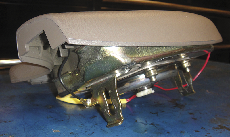
If you remove an airbag, store it with the metal side down; bag side up. If it goes off for some reason, you’ll have a loud pop and you may need to take a tranquillizer, but the airbag will likely stay in the same position. If it’s stored with the bag side down and goes off, it will launch and is more likely to cause damage or injury.
Impact sensors can be tripped by vibration and shock during repair; impact wrenches and hammers should not be used near SRS sensors with the key on. Redundant safety systems will probably prevent airbag activation, but do you really want to gamble on it?
SRS Cast of Players
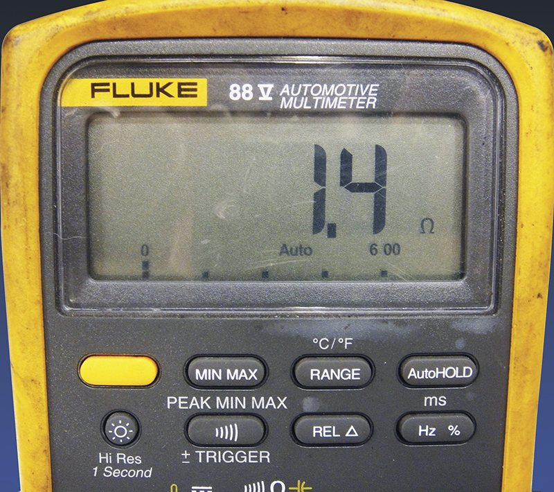
An ohmmeter is sometimes used in SRS diagnosis, but ONLY when the service manual calls for it and ONLY in the manner described in the service manual.
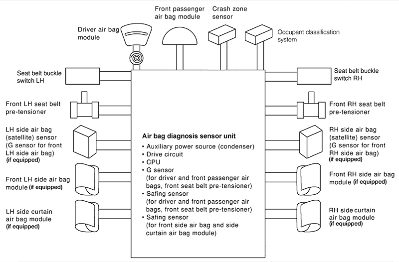
SRS systems have come a long way since the single driver’s side air bag found in vehicles of the late ’80s. Older SRS ECUs had only one sensor and two output choices: to deploy the driver’s air bag or not. Modern systems have a myriad of sensors and a variety of output choices. The system tailors its response to match the requirements of both the occupants and the collision, analyzing sensor data, making decisions, and taking action in thousandths of a second. Here are some of the players found in the modern SRS system:
Outputs
The driver’s front air bag will deploy when the front of the car hits something (or something hits it) hard enough to cause sufficiently rapid deceleration. The driver’s air bag module is located in the center of the steering wheel. Modern units are dual-stage, so they can better match the force of inflation to the force of the collision.
The passenger’s front air bag is also designed to protect against injury during a head-on collision. The front passenger air bag module is located in the dash on the right side of the car. These too are dual-stage on newer Nissan vehicles.
The side air bag modules are located in the outer edge of the front seat backs, one in the left seat and one in the right seat. The side air bags will deploy only when the vehicle is struck (or strikes something) from the side. Don’t be confused by the naming conventions found in the CONSULT and in the service manual. They are sometimes listed as the “Front LH side air bag†and “Front RH side air bagâ€, which sometimes leads technicians to mistakenly believe that side air bag trouble codes were caused by the front air bags. The front air bag modules are almost always referred to as “driver’s†and “passenger’sâ€.
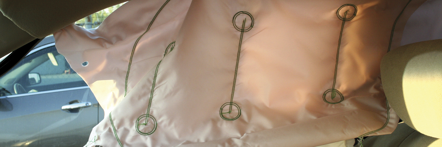
Side curtain airbags are usually found running above the doors in the outer edges of the headliner on either side. They are designed to protect the occupant’s head during a collision, whereas the side air bag modules protect the occupant’s torso. The side curtain (head) airbags are deployed whenever the side (torso) airbags are activated.
Seatbelts are also SRS outputs. In the event of a collision, the Air Bag Diagnosis Unit (SRS control unit) will activate seat belt pre-tensioners to remove the slack from the seat belts. Once the occupant’s weight is thrown against the seat belt, a load limiter built into the seat belt will release some of the belt tension if it exceeds a specified level.
The seat belt and SRS warning lights are also important outputs. If either light is on while driving, the restraint system may not offer the protection it’s capable of delivering.
Inputs
The SRS Diagnosis Sensor Unit is both an input and a control unit. It monitors sensors and activates outputs, but it also contains several built-in sensors and has other functions:
- A “G” sensor to measure the intensity of deceleration/acceleration.
- Safing sensors. Safing sensors are on/off “weight and spring†switches added as secondary confirmation of a collision to prevent inappropriate deployment. There is usually one safing sensor for the front air bags and pre-tensioner and another for the side air bags and curtain air bags.
- An auxiliary power source in case of power failure during a crash. The power stored in the capacitors is why waiting for three minutes after disconnecting the battery prior to working on the system is necessary.
The seat belt buckle switch is actually two redundant switches. With the seatbelt connected, the SRS Diagnosis Sensor Unit expects to see one switch open and the other closed. When the seatbelt is disconnected, the switch positions reverse. This way, if a switch fails, the SRS unit will be able to tell and will set a code. The SRS system will activate the front air bag if the seatbelt is not latched, so these are important inputs. Currently, most cars only monitor the front seatbelts.
Crash Zone Sensor
The Crash Zone Sensor is the first to report a frontal collision. It’s typically located near the front bumper and provides early warning to the SRS Unit. Its electrical impulse will reach the centrally-located SRS Unit before the force of the shock wave.
The left or right satellite sensor will be the first to report a side impact. They are usually located in the lower “B†pillar area (behind the front doors) and will provide early warning of a side impact to the SRS Unit.
Occupant Classification System
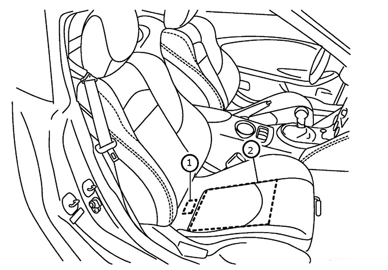
The Occupant Classification System (OCS) is basically a scale in the right front seat. It consists of a sealed mat filled with goo, a pressure transducer, and a control unit. When a passenger sits on the seat, his weight increases the pressure of the goo in the mat. The pressure transducer measures the increase in pressure, and the control unit calculates the weight of the passenger. The OCS unit sends the weight information to the SRS unit, where it is used to determine appropriate activation of the passenger air bag during a collision.
Harness and Connectors
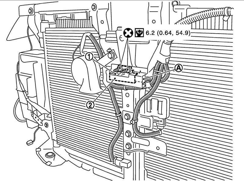
The Crash Zone Sensor is mounted in the front of the car so it’s able to report head-on collisions before the shockwave can reach the occupants.
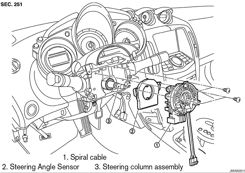
The spiral cable is one the few moving parts (the seat belt switches being another) in the SRS system. The spiral cable sits behind the steering wheel and allows a continuous electrical connection between the driver’s air bag module and the SRS unit as the steering wheel is turned.
SRS harnesses are color-coded in yellow to make them easier to identify. The wiring and connectors are top quality, and design and layout are always very well thought-out. Harness failure is rare unless it has been changed from its original configuration. Always reinstall retaining clips and preserve the original routing when disturbing SRS harnesses for any reason. Never attempt to repair an SRS harness unless the manual or TSB specifically call for it, and then only in the exact manner described.
SRS connectors are easy to work with, if you know how they work. They all come apart easily, with almost no force. If a connector seems difficult to disconnect, you haven’t found its secret yet. Resist the urge to indiscriminately pry on connectors with a pocket screwdriver; check for the connector operation in the manual instead.
Many SRS connectors contain shorting bars that will short its pins together to prevent accidental deployment due to static electricity or improper testing procedures, but don’t take this for granted. Also, keep it in mind when testing, especially when a flow chart test procedure doesn’t seem to make sense at first glance. The presence of shorting bars is often considered in the design of diagnostic procedures, but not explained in the procedure. Before deciding there must be a misprint, remember to allow for the existence of shorting bars.
SRS Diagnosis
The first step for diagnosis is observation of the SRS light. When the key is turned to the ON position, it should light for about seven seconds, then go out. This indicates everything is OK. If the light stays on, the airbags or pre-tensioners may have deployed. If the light blinks, there is a current problem. If the light does not come on, there is a problem with the control unit or warning light circuit. This non-intrusive observation is referred to as “User Mode†in the manual, and is designed to inform the vehicle operator (and the technician).
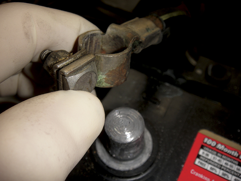
Before diving into diagnosis, test the battery. Low voltage caused by a weak battery will cause all sorts of havoc and will lead to a misdiagnosis if you follow the flow chart without checking this basic element first.
After confirming an SRS malfunction with the warning lamp, use the Nissan CONSULT scan tool to check for current or past trouble codes. If you find codes, check for TSBs before proceeding. You can read through the TSB abstracts on www.nissan-techinfo.com or www.infiniti-techinfo.com, even if you don’t have a subscription yet. This way, you’ll have access to the most current information, which is especially important if you’re working on a late model car.
Nissan usually provides a procedure for diagnosis and repair without using the CONSULT, which can be found in the manual in sections labeled “without CONSULT.†However, it almost always takes more time and often provides far less information. A CONSULT will pay for itself quickly in time saved.
You may notice that many of the diagnostic solutions may at first appear to be a bit heavy-handed. Be sure to read carefully! The diagnostic information and flow charts found in the manual do not lend themselves to jumping around while reading. Be sure to start at the beginning of the section and read all the text in order. Don’t just jump to the beginning of the trouble code flow chart or scan through text looking for information that seems relevant to the problem at hand.
For instance, if you look at a typical driver’s air bag module trouble tree, it may seem at first that the procedure is to test the clock spring with an ohmmeter, then replace the airbag, harness, and control unit. However, if you read carefully, you’ll find the intent was to recheck for trouble codes at the end of each step. Don’t assume important information will be repeated with each step. Read from top to bottom and pay close attention.
Post Collision Repair
Non-specializing body shops often need help with SRS repairs. You may get calls asking if you “have the special tool to turn off the SRS light.â€Â After a collision with airbag activation, several components will need to be replaced to restore system function. You’ll find a list of which components to replace in the SRS Airbag section of the manual. The list will vary, depending on the type of impact. Permanent codes will set and cannot be reset with the scan tool or by removing power; the component must be replaced to clear the fault.
Used or “remanufactured†components should never be used. Just because it may be possible to clear permanent codes with a bit of hacking, does not make it a good idea. The idea behind permanent codes is to protect the user from driving with an unreliable component. Erasing the warning and sending the car out in an unsafe condition is unethical, probably illegal, and certainly a liability.



0 Comments