

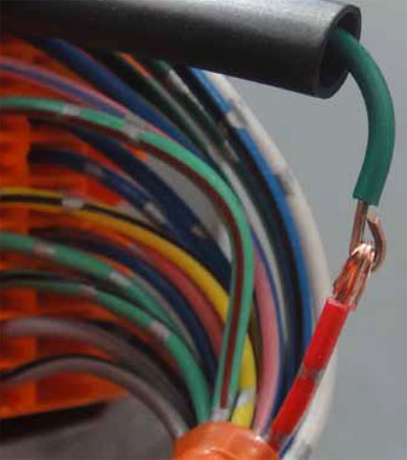
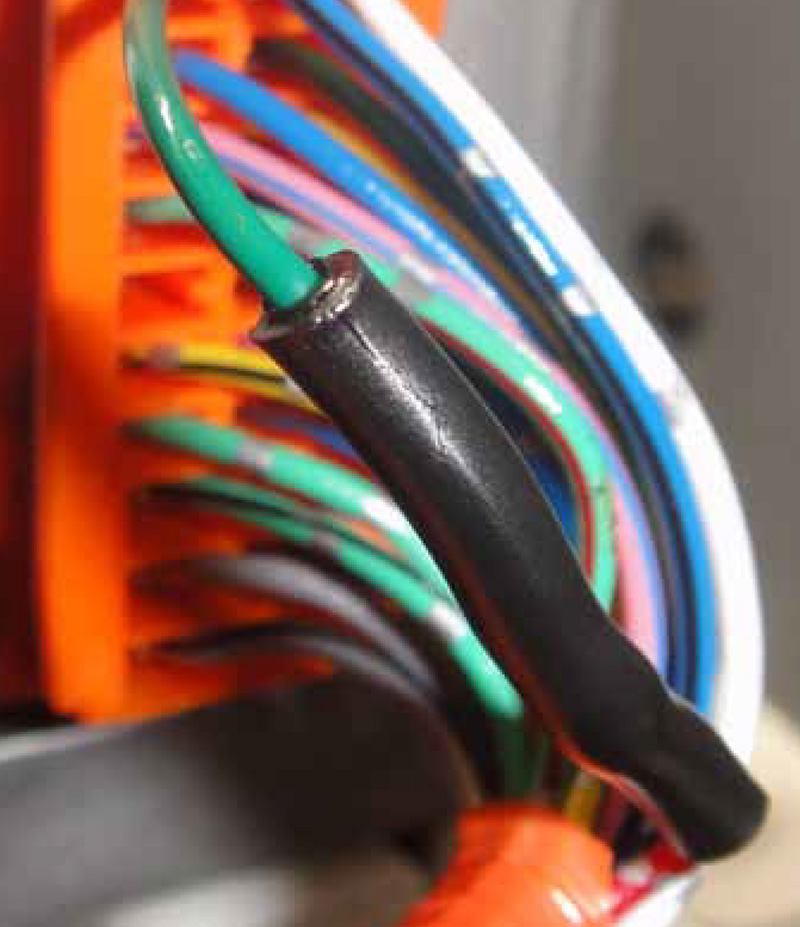
Paul gets to enjoy practicing his old-fashioned soldering skills and saves his customer lots of money.
One of the chief benefits of previous experience with a pattern problem is the ability to make short work of its diagnosis. The effort you put in struggling through your first couple of exposures pays dividends on subsequent encounters. Once a system is committed to memory through first-hand experience, you can diagnose with just a quick skim of the manual, or maybe no reading at all. When a familiar pattern begins to emerge, you’ll know what to do and the quickest way to do it, giving you a distinct advantage.
Faster diagnostic time can mean more money for you, or your customer, but usually a combination of both. Charging less and earning more is a win-win. You’re a hero to your customer, making good profit, and everything is good in the world.
So, when you see a P3006 (Battery levels unusually different) for the umpteenth time, it may be tempting to skip over the relatively easy diagnostic steps, and use an even easier self-created flow chart:
- Is P3006 stored? Yes.
- Is Delta SOC% over 20%? Yes.
- Must be a bad battery pack, because that’s what it has been the last 20 times I’ve seen a P3006.
- Diagnosis done. Profit!
If you have no idea what P3006 is, or what Delta SOC% means, don’t worry. I’ll be briefly explaining the basics P3006 diagnosis, then exploring one of several cases where being a little too arrogant and lazy could have taken me from hero to zero pretty quickly.
A quick review of the basics
The Gen1 Prius has a 274V battery pack made up of 38 7.2V batteries wired together in series. Battery voltage is monitored every two batteries, and can be viewed in the Datalist as battery blocks 1 through 19. Current flowing to and from the battery pack is monitored with a current sensor, and battery temperature is monitored with five temperature sensors inside the battery case. The Battery ECU uses these primary inputs to determine the batteries’ state of charge and state of health, and then shares this information with the HV ECU to help guide its decisions.
P3006 is a common trouble code for the HV Battery ECU. It usually occurs somewhere beyond 100,000 miles on the Gen1 Prius. The newest of the Gen1 Priuses are now nine years old, so almost all of them are candidates for HV battery problems.
Typically, a P3006 will be accompanied by a P3000 in the HV ECU, and a P3011-P3029 in the HV Battery ECU. The P3000 is usually only an indication that there is a trouble code stored in the HV Battery ECU, so when both a P3000 and a P3006 are stored, I tend to ignore the P3000.
P3011-P3029 are codes that point to a specific battery block that is bad. A battery block is two 7.2V batteries tied together in series and monitored as a block by the HV Battery ECU. Attempting to replace an individual battery block is futile. I was told this long ago by a fellow who knows more than I do, and chose to ignore it. If you enjoy Whack-a-Mole, go ahead and experiment for yourself. Focus on the P3006, and think of the battery pack as a whole.
The “normal” diagnosis
There have been several articles (including my own), as well as classes, where P3006 diagnosis has been discussed. Since the information is already out there, and this article is focusing on the exception to the common diagnostic conclusion, I’ll keep this section very brief.
Diagnosis of a P3006 is basically a load test of the battery pack. The load for the test is provided by MG2, the main motor/generator that captures power during regen braking, assists or provides power for forward movement, and is the sole provider of power in reverse. The battery is loaded by putting the car in reverse, and stepping on the gas and brake at the same time.
Just as in a standard battery load test, the voltage is monitored while the battery is under load, but instead of monitoring the total battery voltage, the 19 individual block voltages are monitored. The idea is that if all of the cells have equal capacity, their voltages should remain similar while being subjected to strain.
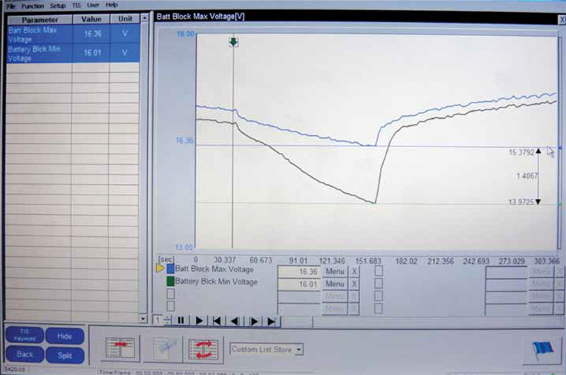
To make simultaneously monitoring 19 PIDs easier, the HV Battery ECU has two PIDs to make the job more human-friendly: BATT BLOCK MIN V and BATT BLOCK MAX V. These PIDs represent the highest measured block voltage and the lowest measured block voltage; they do not correspond to any particular block number. For example, the MIN V may be the voltage reading for BLOCK 1 one moment, and BLOCK 12 the next. This provides an easy way for a technician to monitor the spread between the block with the highest voltage versus the block with the lowest voltage without trying to scan 19 PIDs at the same time.
The maximum separation between the lowest and highest block usually occurs at the end of the load cycle, which is about 40% SOC (State Of Charge). When the battery SOC% reaches 40%, the ICE (Internal Combustion Engine) will start using MG1 to recharge the pack. So the test goes like this:
- Set the Techstream up to record the HV Battery ECU PIDs
- Ready the car and put it into reverse while holding the brake.
- Wait for the ICE to stop (usually around 60% SOC)
- Step on the accelerator to load the battery pack until the ICE starts again
- Graph the recorded data and check the spread between BATT BLOCK MIN V and BATT BLOCK MAX V. It should not exceed 1.2V and is usually less.
Delta state of charge, listed as DELTA SOC% in the data list, is the difference in the calculated state of charge between the lowest pair of batteries and the highest pair of batteries. This PID represents the highest difference measured, not the current difference. Delta state of charge PID starts at 20%; differences under 20% are not displayed. DELTA SOC% should always be 20% if the battery pack is healthy.
Atypical problems
That covers the basics of “normal†P3006 diagnosis. Now, let’s take a look at how P3006 diagnosis can get a little tricky.
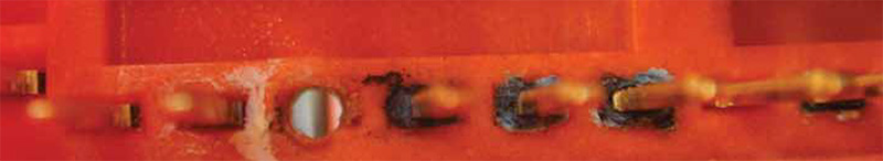
So, when is a separation between the minimum block voltage and the maximum block voltage not a problem with the battery? Well, have you ever made a bad connection with the test lead of your voltmeter? A bad back-probe connection can really screw up a diagnosis! The HV Battery ECU is monitoring block voltages via sense wires, which are much like the leads on a voltmeter. A bad connection on the bus bar or in the HV Battery ECU will fool it into believing the pack has a problem. A smart tech will always confirm a failed test by testing in another way. The HV Battery ECU is not that smart.
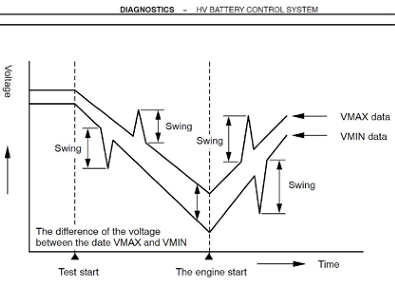
The difference between a bad battery and a bad connection can be observed from the comfort of the driver’s seat using the same data and graph created for P3006 diagnosis. What we’re looking for is large jumps in the MIN BLOCK or MAX BLOCK voltages. Little jumps in battery block voltages are normal. Remember that the MIN and MAX blocks are not real physical blocks, and the voltages will jump around a bit as it shifts from one block to another. However, large rapid jumps usually indicate a connection or ECU problem, rather than a battery problem. Toyota’s flow chart does not acknowledge the possibility of sense wire failure, but it is one of the more common of the atypical causes of P3006 codes.
This type of repair might not become very popular, and that’s probably for the best, but it is a lot of fun to actually fix things on occasion.
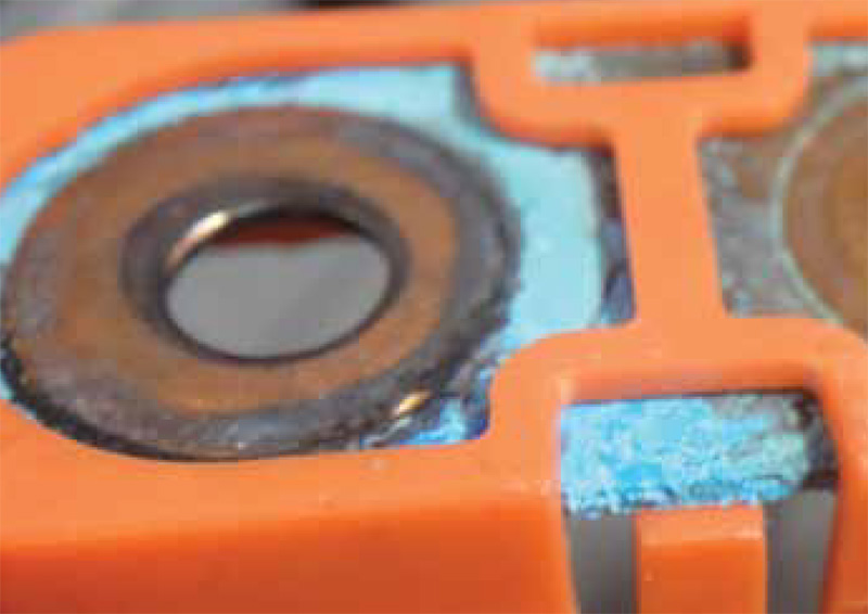
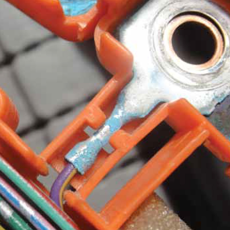
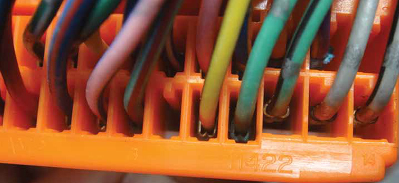
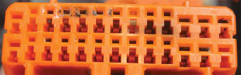
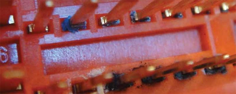
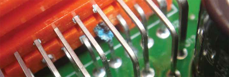
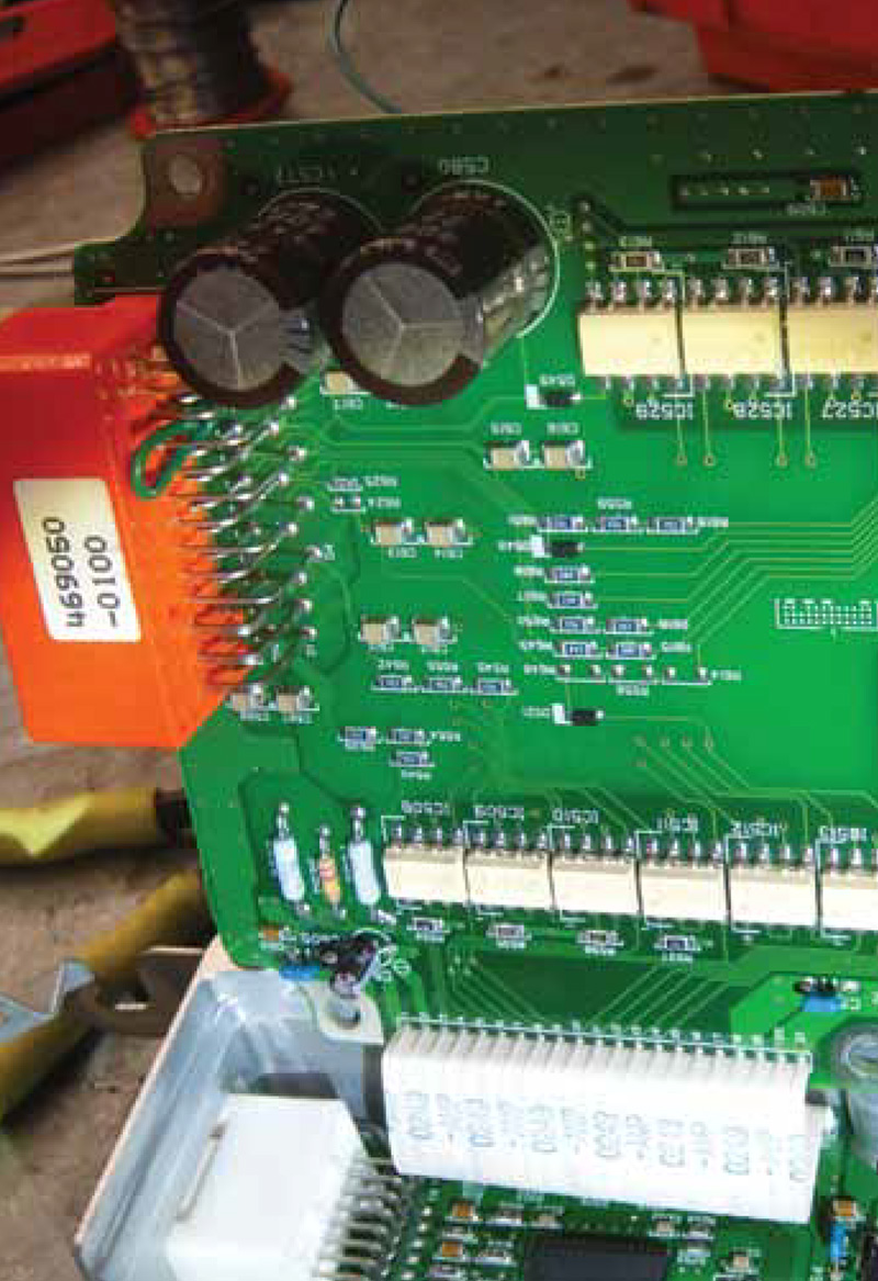
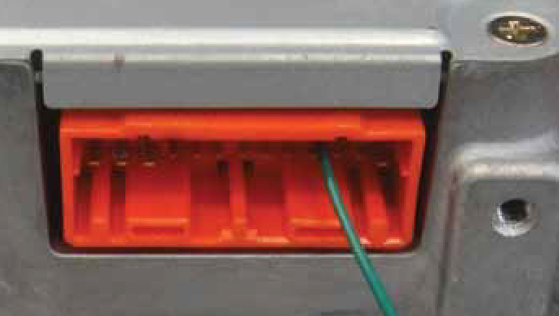
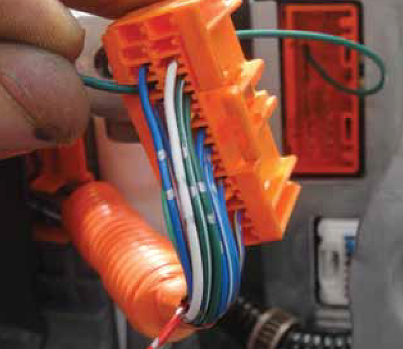
The following is a photo journal of an HV Battery ECU repair.


0 Comments