

My old friend Ray once told me, “Do you know what NEW stands for? Never Ever Worked.” Just because you put on a new part doesn’t mean it’s going to fix the problem. Such was the case with going to fix the problem. Such was the case with this Toyota Camry that had a fresh O2 sensor.
People have their own approach to doing things. I’m no different. While I try to improve my diagnostic processes, mistakes are made along the way. I have to admit my mistakes and learn from them. I really have to think about why I made the mistake and realize there were probably a few more tests I could’ve performed before I started changing parts. But this is a business and sometimes I don’t have the time to test everything to death. Some testing is very time consuming indeed. It is hard enough to get paid for my diagnostic time in this tough economy, and the ones who are willing to pay won’t be for long if it takes two and three visits for the same problem.

Most of us operate in the middle of the two extremes. Some of us pull a code, do minimal scan-tool testing, and go to our trusted information source and look at the “top ten list†of parts that are typically needed to fix the problem. Some of us follow the DTC flow chart, do some detailed testing, and, if all else fails, consult a pattern failure diagnostic database.
If you’re reading this, you’re probably in the latter category. You read these articles to acquire some technical knowledge about a particular system, or you may just want to learn from what someone else went through. Either way, you want to improve your knowledge base. We applaud you. There is very little continuing education in our field. Once every few months automotive technical conventions with training classes come along, but with the rate at which new systems are put on vehicles it’s almost impossible to keep up with the changes. But the responsible among us do what we can.
The subject here, a 2003 Toyota Camry, presented a problem that might have been taken care of in five minutes instead of five hours. It all started on a warm winter day (the North east didn’t get hit with much cold or snow this year). The first tech to look at the vehicle was told that the “check engine light” (more accurately called a “MIL” for “Malfunction Indicator Lamp”) was on and immediately “scanned†for DTCs (actually, you “read” codes, and “scan” for data). He was rewarded with a few. In many states that have vehicle inspection programs, car owners will drive around with the MIL on if their automotive repair shop says it’s okay. Then, when it’s time to do the inspection other problems may have come up.
There was a P0032 and a P0128. The first means the coolant is taking too long to get to the temperature the engine management system requires to go into closed loop. In most cases, this would be a weak or stuck-open thermostat, but this time the coolant level was a little low, so I pressure tested the system, found a small leak, and replaced a hose with new clamps. In the interest of self-preservation, I decided to sell a thermostat. There is little that is more difficult to do than to explain to a customer that the MIL came on again right after you repaired the vehicle, but that this time it’s a different problem. You and I know that any given vehicle can flag any number of hundreds of codes, but try explaining that to the man. It was safer to replace the thermostat, flush the cooling system, and refill it with the correct coolant mixture. In the future, if you would like to know how to diagnose a P0128, you can start by monitoring the coolant temperature sensor signal voltage for 15 to 20 minutes and see how far the signal voltage drops, but you would need some experience with the characteristics of the engine you are working on.
You can also watch the CTS voltage fluctuate when hot. It should remain stable while the engine is running. I’ve noticed that a weak thermostat opens and closes in wider swings and at lower temperatures than normal, so the CTS signal voltage moves up and down more than with a new thermostat. As with most customers around here, this one needed the car for the weekend and would bring it back if needed. I didn’t have the time to let the vehicle cool down to properly test the warm-up period. The engine started right up, so it was not a life-or-death situation. The customer just wanted the vehicle to pass inspection, which is not unreasonable.

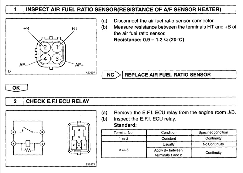
I still had the second code to deal with. A P0031 indicates that the heater circuit voltage is low for the bank 1, sensor 1. If you go through the flowchart for this code, one of the first tests it has you perform is to check the resistance of the heater circuit. I could have gone to the PCM to check this, but in the interests of time I simply checked the resistance of the heater right at the O2 sensor connector.
What I found was no resistance at all. The meter read “OL,†which means “Out of Limits.†You don’t have to be an expert diagnostician to know that an open circuit is probably going to set a code from the comprehensive component monitor in the PCM. This was a fairly simple diagnosis. The heater circuit in the O2 sensor itself was open. A sensor was promptly ordered and installed. Some shops stop right there. They return the vehicle to the customer and let him or her drive it to see if the MIL comes back on. Not anyone who’s reading this article, I hope. The vehicle was taken out on a test drive and codes were checked again. Unfortunately, the MIL came back on, and now there was a code P0032.
With time running short, another sensor was ordered and installed. Once again, the code returned during the road test. I was starting to get worried that the O2 sensor heater driver in the PCM might have been damaged by the old sensor. However unlikely, it is possible. The first test I performed was to verify the code. Sometimes simple mistakes can lead you down the wrong path. The code was correct, so the next step was to verify that the correct part was installed. With Toyota you have to be careful when ordering O2 sensors around the 2000 model year. Toyota used different emissions controls depending on the vehicle’s destination, so it makes a difference if the vehicle has the Federal or California emissions system. Starting in the ’98 model year, the Camry with the California emissions package uses an Air-Fuel Ratio (AFR) sensor instead of an oxygen sensor for the feedback system. Federal models still used a conventional zirconia O2 sensor that generates signal voltage according to how rich or lean the mixture is — above .5V for a rich condition and below .5V for a lean condition.

An Air-Fuel Ratio sensor works differently from a conventional O2 sensor. You cannot monitor signal voltage anymore. The PCM varies a milliamp signal to the sensor depending on a rich or lean condition. You would have to monitor the milliamp signal to see if the sensor is responding. The AFR sensor can accurately read mixtures as lean as 22:1, so that’s why it’s being used more and more by manufacturers. Because of stricter emissions standards in and around the New York Metropolitan area, vehicles with California emissions systems are being sold there. Always look at the emissions sticker, which is usually stuck to the hood or radiator support. The more important issue here is that these sensors will only work in a very specific temperature range. They typically need to run hotter than conventional O2 sensors. Some manufacturers use the signal voltage of an O2 sensor to “interpret†if the heater is functioning. Other manufacturers monitor the amp draw of the heater circuit. With AFR sensors, every one we’ve seen directly monitors the amperage of the heater to verify it is working. This is part of the comprehensive component monitor so the code can flag right away, and, after clearing the code and running the engine, it did.
I could have gone in any number of different directions here, but I’ve been taught that sometimes you have to go back to the beginning. When dealing with a heater circuit code, I always verify that I have 12V on the power supply line, and I did. I then checked the resistance of the sensor, which was approximately four ohms. I then checked the voltage on the ground side to see if the PCM was controlling the heater ground, and it was not. The code was still logged in the PCM, so I tried to clear codes to see what would happen. I noticed the voltage fluctuate between five and nine volts, then after a minute or so the voltage control flat-lined at 12V. I then checked for codes again and there is weren’t any, so I tried to check for pending codes under OBD II generic and there is was, a P0032. This means once I cleared the code I only had a few minutes to monitor the situation before the code flags and the PCM gives up trying to control the ground on the heater circuit. I needed to look a little more deeply into things.
I could see that the PCM was attempting to control the ground of the heater circuit, and, therefore, the amp draw. I wanted to look at the draw to see if it would tell me anything. Now, to measure amperage you need to connect your DMM in series. This means you cannot just tap into the wire as if you were measuring voltage. I had to open the circuit and connect the test leads to each side of the open circuit. This usually means cutting a wire. Now this is not a terrible thing to do, but you probably do not want to cut into the car’s harness, so you are going to cut either the power or ground wire of the heater circuit of the sensor’s pigtail. It doesn’t matter which wire you measure the amp draw on since both sides will read the same amperage. You just have to remember to connect your leads following the direction of current flow or you’ll get a negative reading. I have a low-current inductive probe, and I find it works pretty well compared to a DMM. I saw the amperage oscillate between .5 and 1.8 amps. These seemed to be normal readings but I needed something to compare them to. I felt it was time to pull out the big guns.

I wanted to see what the PCM was doing to manage the situation. I pulled out my oscilloscope, tapped into the ground side of the heater circuit, and cleared the code once again. What I saw was interesting. The PCM did try to ground the heater. I set up the trigger on the scope and could catch one on/off cycle of the heater control. I could see the duty cycle to ground was moving back and forth between 20% and 80%. The PCM made several attempts at increasing the duty cycle (to ground) from 20 to 80 percent until finally giving up. The scope signal flat-lined at 12V again and the PCM flagged a code for the O2 sensor heater circuit. This told me several things. The ground control pattern looked clean. The voltage signal dropped down from 12V cleanly to ground and returned to 12V cleanly. No irregularities in the pattern at all. If I had seen an erratic pattern, I may have concluded that the PCM driver could not control the heater circuit properly. This pattern told me the PCM driver seemed to be in good shape. I was going to have to try a few more things before I replaced the PCM.
I was starting to get worried. Nothing in my testing jumped out at me to say, “Pick me, I’m the problem.†I dreaded telling the customer he needed a new PCM after selling him the idea of a thermostat and an O2 sensor. If you have to look at a problem too deeply, chances are you missed something. When it doubt go back to the beginning. This is something I should have done several tests ago. I went to my information system and pulled up a flow chart for the code. In reviewing the testing, I noticed the first step of the test was to measure the heater resistance on the sensor, which should be between .9 and 1.2 ohm. If you remember (and I didn’t right away), it measured 4.0 ohms. I did verify this as a California emissions vehicle and I did order the correct sensor for it. Why did ours measure 4.0 ohms? I ordered another one and the same thing!?!? I decided to try a Federal O2 sensor. It is still an AFR sensor, yet this one measured about 1.0 ohm on the heater element?!?! This is what the flowchart was telling us. Was this service information wrong, was the part we ordered boxed improperly, or was the PCM flagging a false code for some reason?
The cheapest option was to just try the Federal AFR sensor. Guess what? The draw stabilized at 2.3 amps and the PCM did not flag a heater code after five minutes of running. The duty cycle on the heater circuit stabilized at approximately 25%. After the road test there were no pending codes and no two-trip codes. Simply checking the resistance of the new part would have brought us here a lot sooner, but hindsight is 20/20. It would have been easy to verify the resistance compared to the flowchart when the part came in, but I put the flowchart down when the new part arrived. I talked to a Toyota dealer and found that when ordering AFR sensors they always ask for the part number on the sensor itself. This avoids any confusion when ordering AFR sensors. I don’t know if the catalog was wrong, the part was in the wrong box, the counterman got it wrong, or all the planets were simply aligned against me. But I was finally able to deliver the vehicle that night without replacing a PCM, but I did have to go through a few O2 sensors before I got the right one. “You know what NEW stands for?, Never Ever Worked!†Go figure.
Download PDF


0 Comments