
Mercedes-Benz’s pursuit of safer vehicles incorporates individual systems working in concert to control speed, handling, and stopping. One critical part of this is the Electronic Accelerator. Here’s how it works and how to fix it.

Later throttle body assemblies are true “fly by wire†because there is no longer a cable coming out to the throttle assembly. A pedal sensor is read by the ME control unit, which commands the throttle plate to open for acceleration.
It all started with Mercedes-Benz in conjunction with the Robert Bosch Corporation in the mid-1980s. The companies worked together to develop a CAN (Controller Area Network) that debuted in the early ’90s on the 140 chassis. CAN allowed individual system control units, such as the ME (Motor Electronics), ABS/ASR/BAS (Anti-Lock Brake System/ Anti-Slip Reduction/Brake Assist System) and EGS (Electronic Gearbox System) to co-operate in the control of the vehicle when traction is suddenly lost. In following years, the suspension computer of the chassis CAN was added, and ESP (Electronic Stability Program) combined the drive CAN and chassis CAN. By incorporating an electronic throttle system that reads inputs from various sensors and modules, the driver’s control can be enhanced, and traction is restored by closing the throttle until the tires regain their grip on the road.
The Electronic Accelerator continues to open the throttle if input indicates that the driver still wants to accelerate. An added feature is that the electronic throttle can also handle cruise control functions and idle speed. No longer was a separate cruise-control actuator and idle speed motor needed to maintain vehicle speed and engine idle speed, respectively. The Electronic Accelerator can be commanded to open to maintain the selected speed. While this adds complexity to engine management, in another way it also streamlined it. With all of these control units on a CAN, the self-diagnostic system can monitor all inputs and outputs and display them in diagnostic software. In earlier years, you would have had to interrogate each system for DTCs (Diagnostic Trouble Codes) and manually check the signal values at each input and output to diagnose a problem. Now, the Mercedes-Benz SDS (Star Diagnostic System) allows you to look at the data on the CAN, saving time if you have to isolate a problem.

The first Electronic Accelerator design had a conventional cable at the throttle assembly, but it only drove a sensor in the assembly. Here is the second-generation Pedal Position Sensor. A cable still drives it, but it has two potentiometers to indicate the pedal position.
You can and should interrogate the EA system with your SDS. If in addition to using SDS, you want to manually check signals at the control module connector, please remember that damage to the wires, connectors, or pins will most likely require that the entire harness be replaced. If the computer-controlled system sees any abnormality with EA inputs or outputs, the control unit enters a “limp home†mode and prevents the throttle from opening and the vehicle from accelerating. Many safety measures were incorporated into EA hardware and logic. The first item you need to know about is that there is a redundant system on later models just as you have on an aircraft. Two sensors perform the job of one so they can crosscheck each other.
Inputs
In order for an EA system to work, it needs to know what the driver’s intentions are, and this is accomplished by means of sensors that report on the position of the gas pedal. In the early 140 chassis these sensors are mounted in the EA unit (throttle assembly) between the MAF (Mass Air Flow) sensor and the intake manifold. Linkage from the pedal runs all the way up and out to the EA unit, but there is not a direct connection to the throttle plate. Instead, the linkage moves the pedal position sensor. The EA control unit processes the signals and opens the throttle by providing power and ground to a two-wire DC motor. As the motor opens, a second throttle position sensor changes the signal voltage. This sensor lets the control unit know what the actual throttle position is.

This graph of the Pedal Value sensor shows APP #1 starting off at around 0.3V and increasing to over 4V. APP #2 starts off at a slightly lower voltage and only increases to about 2.5V.
For safety, there are two idle contacts in the throttle assembly. These switches indicate when the pedal is in the closed position. One switch is normally open and the other is normally closed with the throttle pedal released. When the pedal is applied, the two switches change states — the open switch closes and the closed switch opens. If one switch were to send an implausible signal, the other would take over, but the throttle would enter a power-reduction mode, and DTCs would set in multiple control units. There is a clutch that decouples the throttle motor from the throttle plate shaft so if the system were to have a major problem the throttle plate will not be opened and the vehicle will not accelerate. In the case of the M120 engine (early V12), the right throttle body is the main unit that has the pedal position sensor in it. The right throttle assembly feeds the left bank of the engine, and the left throttle feeds the right bank as they cross each other through the intake manifold.
Starting in the ’96 to ’97 model years, the HFM (Hot Film Mass) air flow fuel system was upgraded to the ME (Motor Electronics) system. This had separate pedal position and throttle-position sensors. The throttle-position sensors are still in the throttle body assembly, but the pedal-value sensor is mounted underneath the hood and is driven by a throttle cable. There are now two sensors in the pedal-value sensor assembly. They are both still three-wire units, and they have individual five-volt references, signal voltages, and grounds. The voltage increases on both signal lines, but at different rate. The #1 pedal-position sensor signal voltage is roughly double that of the #2 APP (Accelerator Pedal Position) sensor. With a closed throttle, you may see .18v on the #2 and .28v on the #1 sensor. The sensor signals are sent to the ME control unit, which commands the throttle motor to open.

Take a close look at the EA harness connector. A problem here may be the cause of an intermittent throttle code and the customer complaining that the engine goes into limp-in mode. Corrosion at the pins can change the voltage signal enough to set a code.
If the voltages are off by as little as .1 volts, a code will flag and warning lights will illuminate in the instrument cluster. The two sensors cross-check each other. If one sensor sends a bad signal, the limp-home mode will give you up to 60% throttle opening, and response is slowed down. If both signal voltages are incorrect compared to one another the engine will only idle. There is also an idle switch on the pedal. The ME control unit expects the pedal sensor to be at minimum signal voltage when the idle switch is closed. If you were to move the APP sensor manually, you would set a code and engage the limp-home mode because the idle switch would still indicate idle. There is a second Hall-effect type of APP. The connector is slightly different with two squared off corners. The same voltage readings still apply even with the different connector design.
Starting with early- to mid-2000 211 and 220 chassis models, the accelerator pedal-position sensor is mounted directly on the pedal. This must be replaced as a unit. It still has two pedal-position sensors in it. It is a six-wire assembly with two five-volt references, two signal wires, and two grounds. The signal voltages are roughly the same as on the previous design. Pedal-value sensor #1 starts off at about .35 volts with the throttle closed and will increase to approximately 4.5 volts at WOT (Wide Open Throttle). Pedal-value sensor #2 will start off at about .18 volts and increase to about 2.3 volts at WOT. In the service bay, do not expect to see these voltages wide-open. With the engine not running, the throttle will only be commanded open part of the way. Keep that in mind while checking the system.
Changes have also been made on the actuator side. No longer are there closed throttle contact switches in the actuator. Only the signal voltages from the motor-position sensors are used to calculate throttle plate position. These have a six-wire connector. Two wires supply the DC reversible motor to open and close the throttle. The other four are for the position sensors. They share a five-volt reference and a ground, leaving two signal wires. Throttle sensor #1 starts off at approximately 4.3 volts, but this signal decreases as the throttle plate opens. At WOT, you should see about .5 volts. Throttle sensor #2 starts off at about .35 volts and increases to approximately 4.3 volts wide open. The voltages cross-check one another. Theoretically, both signal voltages should add up to about five volts in all throttle positions.

A close look at the signal voltages of the APP sensors in the throttle assembly shows the upper trace starting off at over 4V with the key on and the lower trace starting off under one V. Toward the end of the pattern, under acceleration, one signal voltage decreases and the other increases.
These input signals are sent to the ME control unit, which processes them to control idle speed, cruise control, and rate of acceleration. In reverse gear, the rate of opening is slowed relative to pedal movement. It can also close to reduce engine power if signals come in on the CAN indicating that traction has been lost. This reduction in power helps the tires regain their grip. ME is also in charge of all the limp-home strategies, and monitors the messages on the CAN from the ABS/ASR/ESP and other modules that may affect power application. When the EGS (a.k.a. transmission control module) reports a shift, the ME will retard ignition timing to help with smooth shifting. It also monitors the amp draw of the throttle actuator motor. If the throttle is sticking or binding in the throttle bore, ME will flag a code and go into limp-home as well.
We already described the limp-home mode of the pedal-position sensor: If one potentiometer produces an implausible signal, you will have a maximum of 60% throttle opening. If both sensors send problem signals, you will be limited to idle speed only. There are slightly different fail-safe modes for the actuator. If one sensor’s signal is inappropriate, the throttle opening is once again limited to 60%. However, the second sensor in the actuator and the MAF sensor are used to command throttle position. If both throttle sensors send faulty signals, or the two voltages do not correspond to one another, a spring capsule is activated and throttle opening is limited to 10 to 12 degrees. This will only allow the engine to rev to 1,800 rpm, maximum. Idle speed will be set at about 900 rpm using the injectors for control. If a mechanical fault is determined by the actuator, a safety fuel shutoff program is activated and the injectors will stop delivering fuel at 1,200 to 1,400 rpm.
Cleaning the throttle plate and bore has become part of a regular tune-up, but is even more important today than it was. If carbon deposits are present, the throttle plate may stick, setting an actuator code. Do not spray the solvent down on the throttle plate as it can work its way into the motor assembly and damage internal components. Spray it on a rag and, with the key off, wipe away the buildup. This will only help if you have a throttle actuator code. If there is a problem with an actuator, specific limp-home modes are engaged.

Carbon can build up on the throttle plate and in the bore. The ME control unit will adapt by opening the plate to maintain idle speed. If the battery goes dead, this adaptation is lost and the engine may not idle properly. After cleaning the throttle body, you may have a high idle, so clear all adaptive strategies.
The ME control unit is capable of learning if the throttle plate is restricting air flow at idle and gradually opening up the throttle to compensate, which is known as idle adaptation. If the battery were to go dead, the ME may forget these adaptations.
This could cause a low idle speed, or a deceleration stall after the battery has been recharged. You can simply clean the throttle plates to restore a normal idle. Throttle plate adaptation will have to be performed after a dead-battery incident, or whenever the throttle assembly or the ME control unit has been replaced. You can perform the throttle relearn with your SDS (Star Diagnostic System), or by simply leaving the ignition key on with the engine off for 90 seconds. You should hear the throttle actuate as the throttle body is being adapted.
You can also look at idle adaptation under “Actual Values†with your SDS. These numbers show if the ME control unit is opening the throttle to compensate for a low idle speed, or closing it to compensate for a small vacuum leak.
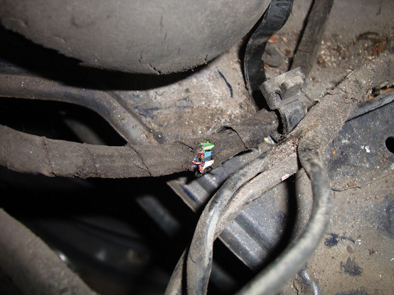
If you have a hard code for the actuator or throttle position sensors, check the wiring harness for physical damage Unplug the connector and check the voltages on the harness side. Here we followed the harness and found multiple broken wires.
There are no special procedures when servicing either the pedal position sensor or the throttle actuator other than the normalizing of the throttle actuator. Each component should read the correct signal voltages once plugged in and installed properly. Of course, each component is relying on a stable five-volts reference and ground (both provided by the ME) to make the correct signal voltages. You should always verify the five-volt reference and ground with your DMM to make sure you do not have any wiring or control unit problems. There are also safety switches in the actuator. They are the ones that indicate that the throttle is closed and at the idle position. The ME puts out a 12-volt reference that the switch either grounds or not to let the computer know the vehicle is at idle. With the connector at the actuator unplugged, you should measure the five-volt reference and two 12-volt references for the closed throttle switches.
Knowing the different limp-home mode strategies coupled with the use of your SDS (available for purchase from Mercedes-Benz, see www.startekinfo.com) will help reduce your diagnostic time and, more importantly, assist you in making a more accurate diagnosis of this critical system. Your customers rely on you to provide service worthy of their Mercedes-Benz vehicles. This dedication to their safety and well-being will keep them coming back.


0 Comments