
Traction Control isn’t just a matter of using ABS to throw torque from one side to the other. It’s an integrated system includingASR, BAS, ESP, and electronic throttle control, which all share data over a CAN. So, you’ve got to look at the big picture during diagnosis.
If you were to ask an engineer what the word “traction†means, you might get an answer like: “Traction is defined as a physical process in which a tangential force is transmitted across an interface between two bodies through dry friction or an intervening fluid film resulting in motion, stoppage or the transmission of power.â€1 In layman’s terms, this means the maximum amount of frictional force between two surfaces without slipping, in our case here the surfaces being the tires’ tread and the road surface.
35 Years for ABS!
Over the years, Traction Control has evolved to include Throttle and Suspension Control. Traction Control’s infancy was the Anti-Lock Brake System (ABS). ABS comprises wheel speed sensors and individual hydraulic solenoids that can apply, hold, and release pressure to each wheel individually. Believe it or not, the first vehicle to have ABS 2 (the original Mercedes-Benz version of ABS) was the 1978 S-Class. Systems more similar to what we have today didn’t appear until 1985, but that’s still 27 years ago.
Wheel speed sensors, by the way, have a function many people don’t know about. Not only do wheel speed sensors provide information about wheel slippage, but they can also detect if the vehicle is riding on rough roads. Vibrations transmitted through the vehicle due to rough roads may have a negative impact on engine smoothness operation, which is why wheel speed signals from the traction control unit are sent via CAN to the ME, which uses this information and changes injection pulse to compensate for these irregularities to ultimately give uniform operation regardless of any driving condition.
|
ASR Intervention Sequence  |
||
| Â |
When 1 Wheel slips: |
When 2 Wheels slip |
|
Below 25mph |
1st: Brake applied 2nd: Torque reduced |
1st: Torque reduced
 2nd: Brake applied |
| Above 25mph |
1st: Torque reduced 2nd: Brake applied |
1st: Torque reduced 2nd: Brake applied |
|
In Turns, at 12mph to 75mph |
1st: Torque reduced 2nd: Brake applied (With lower slip threshold) |
1st: Torque reduced 2nd: Brake applied |
Not Just Dumb Limited-Slip
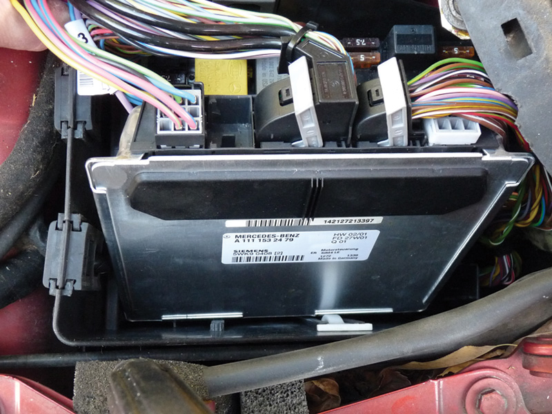
This ME Control Unit is located in the left front fuse box. When the fuse box lid is not securely fastened, it can allow water to get in. Pull the connectors and check for evidence of H2O.
Automatic Slip Control (sometimes called ASR) was then installed on many vehicles. It goes far beyond the capabilities of an old-fashioned mechanical limited-slip differential by providing brake intervention at the rear driving wheels and combining it with engine torque control. This means that if one rear wheel is spinning, that wheel’s brakes are applied, which sends the torque to the opposite wheel on the same axle through the differential (somewhat like an electronically-controlled version of the right and left brake pedals of a typical farm tractor, which can be manipulated by the driver to send power to one side or the other). If both wheels are spinning, a request is made via the engine Controller Area Network (CAN) bus to the Motor Electronics (ME) control unit to retard ignition timing and “relax†the throttle until traction is re-established. The only thing that was added to make this possible was programming in the ME Control Unit and a high-speed CAN line between the traction control unit and the ME.
 possibly damaging the ESP Control Units that are mounted on the hydraulic units.")
Here is an example of an ESP Control Unit on a 2002 C-class. Aftermarket ignition components may not be as protected against causing high electromagnetic field (EMF) possibly damaging the ESP Control Units that are mounted on the hydraulic units.
Brake Assist System (BAS) was next on the scene. BAS provides maximum boost assist in an emergency situation by timing how quickly the brake pedal is applied. Thus, emergency stopping distances are shortened by initiating full braking faster than any driver can move his or her foot.  This is achieved by the use of a BAS Membrane travel sensor (A7/7b1), BAS Release switch (A7/7s1), and BAS Solenoid valve (A7/7y1).Â
Divine Intervention

This is how vehicle oversteering and understeering is corrected by the ESP Control Unit.
The next ingenious evolutionary advance was the Electronic Stability Program (ESP). Working in concert with ABS, ASR, and BAS, ESP prevents over-steering and under-steering by applying the appropriate individual brakes to regain control of the vehicle. This is achieved by the ESP Control Module monitoring a lateral acceleration sensor, a yaw rate sensor, and a steering angle sensor, the signals from which allow the ESP Control Module to decide whether or not the vehicle is about to go into an uncontrolled skid. If its logic says it is, it applies whichever brakes are necessary to regain control and stabilize the vehicle. In essence, no matter how tight the turn you’re making, or how fast you’re going around a curve, or how far down you push the gas pedal, the vehicle will adjust the throttle and apply the brakes on its own to try to complete the handling maneuver safely. Of course, it can’t change the laws of physics, but we’ve heard people who’ve experienced its beneficial effects describe it as “the hand of God.â€Â In other words, almost like divine intervention to prevent an accident.

All of these sensor inputs help the ME Control Unit maintain throttle control.
Who Needs Mechanical Linkage?

The redundant potentiometers of the Electronic Accelerator cross-check the accuracy of the measurements. If one contradicts the other, the ME will put the vehicle into “throttle limp†mode.
A necessary component of maintaining traction is the modern throttle control system. The Electronic Accelerator is basically a drive-by-wire technology where the driver is not in direct mechanical control of the position of the throttle plate. Many people were horrified when they first heard of this concept — “Will the car run amok if there’s an electronic glitch?â€Â It turns out that’s not possible because there are redundant potentiometers in both the B37 sensor (Accelerator Position Sensor) and M16 (Throttle Actuator) to cross-check the accuracy of the measurements. If one of these measurements contradicts the other, the ME will put the vehicle into “throttle limp†(limited acceleration) to allow it to be driven, albeit at a low level of performance, to the nearest repair shop. The input from the B37 sensor is just that, an input, and does not open the throttle actuator. Ultimately, it is the programming in the ME that will receive the input and decide how far to open the throttle as long as there is no over-ride from the traction control module. Throttle Control, which is a part of the ME Control Unit, goes hand in hand with traction control due to the fact that if there is no “true†contact with the road, what is the point of sending more torque to the wheels? You’re not going anywhere anyway. The ME reduces engine torque when it receives implausible or incorrect wheel speed signals that indicate wheel slippage to aid in regaining traction.
Stiff or Stiffer?

If the Electronic Acclerator sensor has any corrosion issues, your testing may indicate that it is out of specifications.
The latest developments in suspension technology integrate traction control as well as throttle control. Systems like Active Body Control (ABC), which is an active hydraulic suspension, and Airmatic, which is an active air suspension both adjust the suspension to any driving condition to keep the vehicle level. This is achieved by receiving ride height and body acceleration inputs as well as wheel speed, wheel rotation, tire pressure, and brake torque signal inputs from the ESP Control Unit to make adjustments that produce harder or softer dampening to conform to any driving style or situation. These signals are transmitted from the traction and throttle control units via a high speed CAN bus at a data transfer rate of 500 kB/S (kilobytes per second).
Info Sharing
Diagnosing integrated functions of traction, throttle, and suspension can be complex because the processed information is shared not only with the module that it is hard-wired to, but with all the other modules relying on that information also. That’s why having a factory-compatible scan tool that has the ability to communicate with all the modules on the vehicle is so important. If you only can communicate with one or maybe two of the many different modules on the CAN bus, the faults in these modules may indicate to you that you may have a failure somewhere else. If you look at what malfunction lights are on as well as what driving characteristics are impaired, it may lead you in an entirely different direction.
The most common of these failures is the dreaded ABS light “Visit Workshop.â€Â Your scan tool shows a P1999 code in the ME Control Unit stating: “P1999 [8] ‘Rough road detection signal†(arrived at by comparing wheel speeds). If you only have a scan tool that will communicate with the ME Control Unit, you would automatically think that one of the wheel speed sensors has failed. Without having the ability to look at the “Actual Values†in the Traction Control Unit to monitor the live status of the sensor, your next plan of attack would probably be comparing the resistance values of each sensor with an ohmmeter. If the ohmmeter reads approximately the same side-to-side, you may take another tack, switch your DMM (Digital Multi-Meter) to read AC voltage, and spin the tire. Again, if the readings are pretty much the same on both sides, now what? This proves that even if you apply experienced trouble-shooting logic, you can very quickly go down the wrong path and waste valuable time.

Version coding the modification year correctly is vital to how the vehicle communicates on the CAN bus. Always verify that the option codes listed on the vehicle data label match what the vehicle is coded to have.
The Genuine Article

Here are the component locations for the ESP system on a 215/220 model.
That’s why it’s essential to get a factory scan tool that can communicate and access the faults in all modules to paint a better picture as to what is going on with the vehicle. If the suspension module, which also gets inputs from the ESP traction control unit, is displaying problems with communication from the ESP, you need to follow the evidence and start investigating what’s happening. Can communication be established with the traction control unit? Are there powers/grounds missing to the control unit? If powers/grounds pass a load test, but no communication can be established, is the CAN bus corroded at the unit, or does the vehicle have coding errors?
You can always hook up a scope or graphing multi-meter to the CAN bus and see if the pattern looks acceptable. Unfortunately, this won’t tell you if there is missing information on the CAN bus. You could have a perfectly fine CAN bus, but only a scan tool will be able to read the information and tell you what is missing.
Another question to be asked is, does the vehicle know how to communicate with the ESP traction control unit? If the “coding†is not correct in the Central Gateway Module (CGW) or Electronic Ignition Switch (EIS) as to what kind of traction control is present, or what modification year it was produced in, the vehicle may not know how to identify or recognize the signal on the CAN bus, even though it is present. For the most part, control units need to be told exactly what kind of vehicle they are installed in. Not only for the sake of that particular unit, but for all the other units relying on the information that it gives. A factory scan tool will give you the ability to read and change coding in all modules that require coding.
When all avenues have been looked at and no other explanation can be deduced other than a traction control module failure, it’s time for replacement, which will again need to be programmed by a factory compatible scan tool. Not only coding, but performing a recalibration of the ESP sensors will need to be done.
As you can see, when dealing with the most sophisticated cars in the world complex situations are apt to arise. That’s why it’s so important to have the real Mercedes-Benz scan tool. Aftermarket units will take you part of the way, but they simply haven’t got the dedicated capabilities you need for complete diagnosis of M-B vehicles.
It’s reassuring to know that Mercedes-Benz has always focused on safety as the Number One priority when designing and building motor vehicles. In doing so, the company has continually set the bar higher and higher for industry standards. |
1Mechanical Wear Fundamentals and Testing by Raymond George Bayer
Mercedes-Benz Traction and Braking AdvancesABS – Anti-lock Brake SystemABS modulates the brake pressure to prevent the wheels from locking up during braking in order to maintain directional control. Introduced in MY1985. 4MATIC – Automatic Four Wheel Drive4MATIC uses a transfer case to distribute power to all four wheels. The traction control system is used to determine wheel slip and the 4MATIC system hydraulically applies clutches in the differential and transfer case to direct the power to the wheels with traction. Introduced in the 124 series in MY1987. ASD – Automatic Locking DifferentialASD consists of hydraulic clutches on the differential that are applied to match the rear wheel speeds when the ABS sensors detect a spinning wheel. Introduced in MY1991. ABS/ASR – Anti-lock brakes with Anti Slip ControlASR uses the traction system to apply pressure to the brake caliper of the spinning rear wheel during acceleration. If both rear wheels are spinning, engine torque is reduced. Introduced in MY1991. ETS – Electronic Traction SystemReplaced the Automatic Locking Differential (ASD) option. Using the ABS components, brake pressure is applied to a spinning wheel during acceleration. Introduced in MY1995. ESP – Electronic Stability ProgramESP includes ABS, ETS and ASR functions, plus it detects directional instability (oversteer and understeer) in the vehicle and uses the brake and throttle control to help keep the car going in the “right†direction. Introduced in MY1996. 4ETS – Four Wheel Electronic Traction SystemA four-wheel-drive system that uses the ABS/ESP components to apply brake pressure to any spinning wheel (or wheels, maximum of three) during acceleration. Integrated with 4MATIC, it falls under that name on today’s passenger cars. Introduced in MY1998. BAS – Brake Assist SystemBAS monitors brake pedal application speed, and if an emergency situation is calculated, maximum brake boost is provided. Introduced in MY1998. SBC – Sensotronic Brake ControlThis “brake-by-wire†electro-hydraulic system includes ABS, Brake Assist and ESP functions. Electronics replace many conventional mechanical components, including the brake booster. Introduced in MY2003. |
Â


0 Comments