
Today’s Volkswagens have some of the most sophisticated computer technology imaginable aboard. Problems in the basic electrical system, however, can disable and defeat it. So, before you get into high-tech computer troubleshooting, check related wires, connections, grounds, etc.
In the 1970s, we technicians had to learn all about newly-developed electronic ignition systems. In the ‘80s, becoming familiar with electronic fuel injection was our challenge, followed by that of airbags later in the decade. The ‘90s brought us CANs and computer-controlled body systems. In the new millennium, we got hybrid technology, and expanded, integrated versions of all the on-board electronics. If we look back at the development of the automobile over the past 40 years, we can only imagine what the next 40 have in store for us.
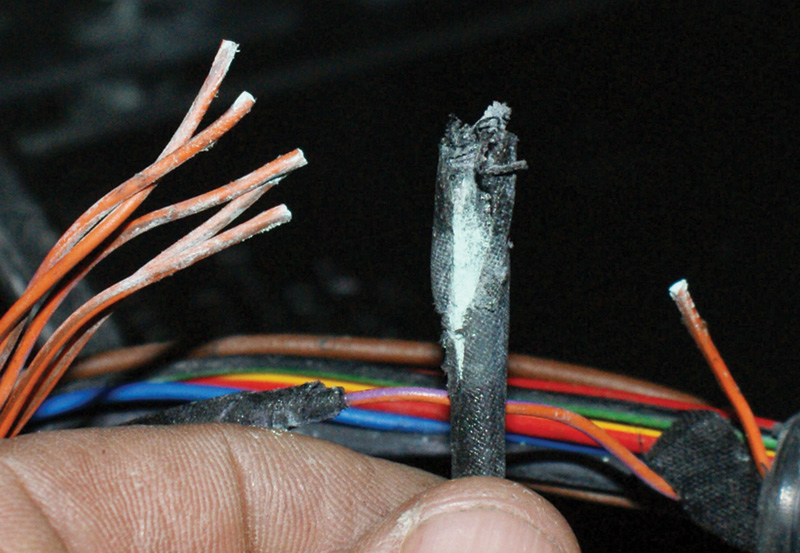
But all this advanced technology depends on electrical wiring and connections — always has, and always will — and they’re susceptible to both the forces of Nature and motoring from water infiltration to vibration and heat.
Every electronic system requires two basics: a power supply and a ground path. Each control unit in the system needs to be supplied with power and ground. Every computer-controlled system is just that, a system controlled by a computer through relays and solenoids. Again, each of these outputs needs an adequate voltage and ground supply. Of course, the control unit relies on a network of sensors to make its decisions, and sensors need a reference voltage supply, a signal path, and a ground as well. Multiply this by the many computer systems in the vehicle and you can see that an extensive amount of wiring is needed. Now, CANs allow control units to share input signal data, thus reducing sensor duplication and wiring. But CAN communication is made up of very fast, but very weak electrical signals that are prone to outside interference. Poor electrical connections can interrupt CAN communication and set fault codes in all the systems involved. Each system and communication network needs to be problem-free if it is going to function properly.
Physics 101: Electricity
Electricity is the movement of electrons through a conductor in order to perform work. Voltage is “pressure†under which the electrons travel, amperage is the number of electrons passing a given point (you could call it “volumeâ€), and the ohm value is the resistance a conductor offers to moving electrons. A typical automotive battery has six cells that produce 2.1volts each. If we wire them together in series (that is, the positive of one attached to the negative of the next), we add up the voltage and arrive at 12.6V. When the engine starts running, the alternator provides approximately 13.8 to 14.2V in order to charge the battery and provide electrical power for the vehicle. So, engineers design automotive components to operate at around 12 to 14V.
Although modern vehicles have a huge number of electrical components, each one can be reduced to a simple electrical circuit. For our purposes here, a circuit is defined as an electrical path that starts at the positive terminal of the battery or alternator, passes through a conductor to a component (in order to perform work) and returns through a ground path to the negative post of the battery terminal or alternator.
Harnessing
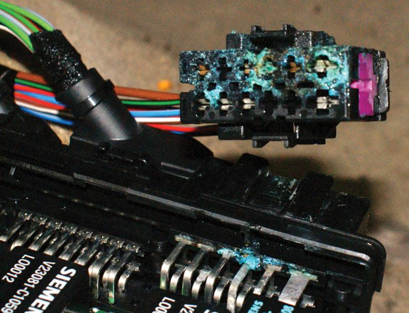
Whenever a problem occurs, it is your job to identify the problem circuit and test it. You are going to need to verify that the voltage supply is adequate and that there is a good ground path. Throughout a wiring harness there may be a few connectors. These make the harness easier to assemble, and also improve serviceability. On the other hand, they are also potential problem areas. Each connector has a male and female blade that fit together. If water or something like a soft drink happens to penetrate the connection, corrosion occurs or deposits develop, compromising electrical contact. Voltage will drop at that point, depriving whatever that branch of the harness serves of its proper amount of power. Of course, this can (and frequently does) happen on the ground side of a circuit also. In automobile electrical systems, voltage is typically sent out along wires to electrical consumers, but the entire body and chassis of the vehicle serves as the ground path.
A poor connection on the ground side will also prevent a component from functioning properly. You may have 12V to the electrical consumer, but if the ground path is poor the current won’t complete the circuit, or at least not to an acceptable extent. You can measure the voltage on the ground side — you should find little or none. If you put the ground lead of your meter on the negative battery post and the red lead on any other ground you should see little to no voltage. Think of your digital multi-meter as measuring a difference in potential. The negative battery post is the perfect ground (or, the alternator case). If your red lead measures almost no voltage, then the wire you are probing with the red lead must be a good ground as well. This is true to a point. The more current that passes through a circuit causes the ground to “work†harder. If the ground path is not up to the task, then voltage will rise on the ground. If the rise is significant, the component will stop working. This is also known as “voltage drop.â€
If a fuel pump starts to seize, the current will rise and the voltage will drop. If the current rises high enough, it can melt the wire — that’s why a fuse is installed in the circuit. When the current is getting to the point where it will melt the wire, the fuse blows and opens the circuit.
Corrosion is a different matter. It prevents voltage and current from passing through a circuit. The electrical consumer will try to draw current, but since the voltage supply to the consumer is inadequate, it will pull the voltage down, resulting in voltage drop. If you measure the voltage to the consumer at this point you’ll see the low voltage on the power supply side of the circuit.
You’ll have to look at the wiring diagram of the problem circuit and isolate where the drop is occurring. Sometimes these connectors can be buried underneath carpeting, so this may not be an easy task. You should start by checking voltage at parts of the circuit you can easily access. The actual component is a good place to start, followed by the fuse box. You should put the ground lead of your meter on the negative battery post, but this may not always be close to where you are working.
Testification!
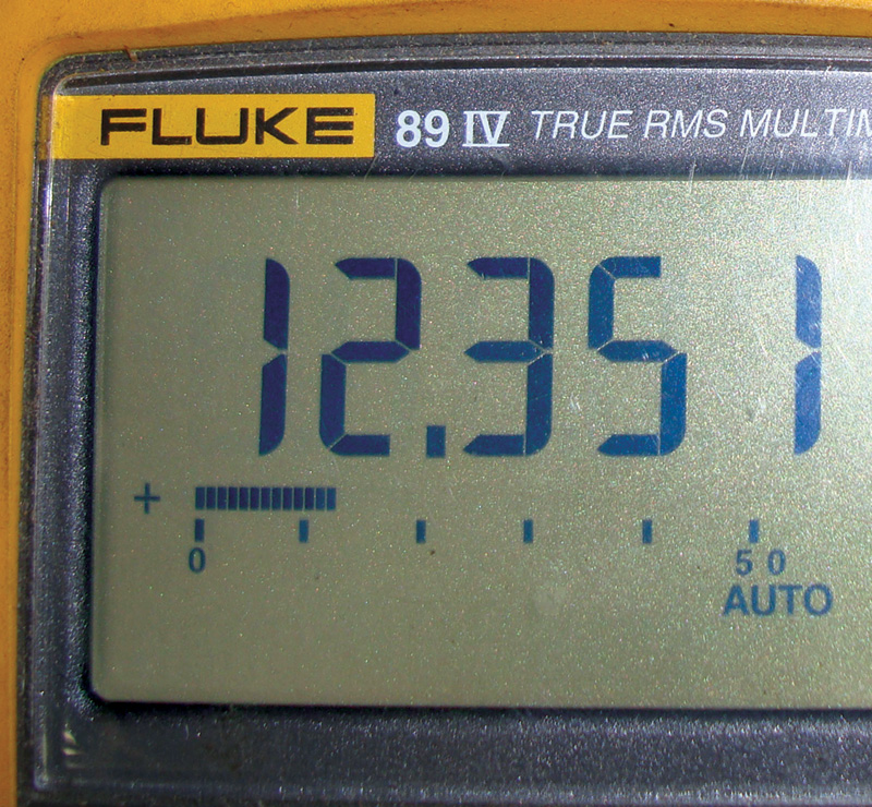
The best tool to use when diagnosing electrical circuits is a Digital Multi-Meter (DMM, previously known as a Digital Volt Ohm Meter, or DVOM). A test light will let you know if there’s power on the circuit, but it will light up if there is anywhere from 6 to 12 V present. Computer-safe test lights that use LEDs instead of an incandescent bulb will indicate a proper ground even if the ground cannot handle a “loaded†circuit (one that is flowing heavy current). When testing for voltage, the best place to put the ground or black lead of your DMM is the negative battery post (okay, maybe the alternator case). You can easily run a jumper lead from the post to your meter and you will be sure you have absolute ground. If you are going to use a body ground, you should still verify what the voltage drop (if there is any) is by measuring the voltage there compared to that at the negative battery post. Keep in mind if you see .5V while testing, it may seem like a small number. But if you’re measuring the voltage on a sensor signal wire, .5V can be a significant difference. Acceptable voltage drop across a connector is .1 of a volt (the traditional standard of .2V is no longer valid).
Now this may not seem like a large drop to you, but let’s look at the overall circuit of an accessory power supply. From the battery, the circuit usually continues to a power distribution hub in a fuse/relay box. If you start off at 12.6V from a perfectly good battery, your first drop across the lug may leave 12.5V (12.6 – .1 = 12.5). Then, it may pass through the ignition switch and that is another .1V or so loss, so now you are down to 12.4V. Another 2/10ths may disappear at the fuse, leaving you with 12.2V. Another connector in the circuit? Perhaps you’ve now got 12.1V. So, you’ve already lost half a volt on a circuit that is functioning normally, and you haven’t even turned the component on! If we measure .5V on the ground side of this consumer, then the actual component is not “seeing†the 12.6V of the battery, but only the difference between the 12.1V that made it through, minus the .5V on the ground. If you were to put your meter across the connector, you would measure only 11.6V.
Results
Remember, the DMM will only measure the difference in potential between the voltage on the power supply and the voltage on the ground. Most consumers will run at slightly lower-than-designed voltage, but corrosion across a connector can drop the voltage by several volts, not just a couple of tenths.
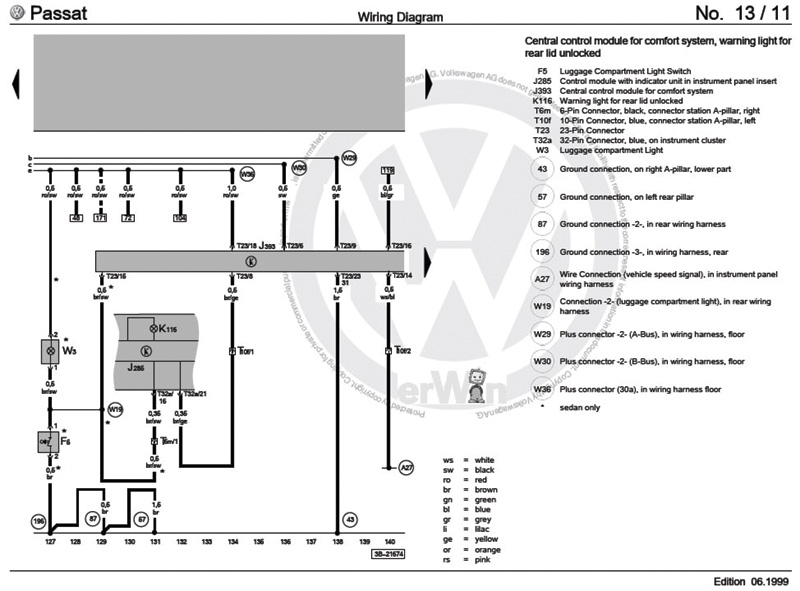
As an aside, it’s always a good idea to add a stable voltage supply from a modern battery charger while testing as you may have the key on for quite some time. Current flowing through the vehicle with the ignition key on will eventually drop the battery voltage to unacceptably low levels for testing. Simply measure the voltage with the battery charger on the vehicle and start subtracting voltage drop from there. If you find that you have close to 12V at the fuse, but that drops to 6V at the consumer, look at the factory wiring diagram available to you at
www.erwin.vw.com and see what connectors are in the circuit so you can locate them for testing. Check the voltage on both sides of any connector while trying to operate the load.
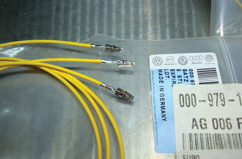
As with any other system, there are rules that have to be followed. Volkswagen is very concerned with the proper repair of its vehicles so that they can continue to operate as there were engineered to do. Subtle modifications can change these operating characteristics. For example, Volkswagen does not want you to solder wires together as a repair. A crimp connector is all that is required. Further, the repair should be wrapped in heat-shrink tubing to protect it from moisture intrusion. Wires that are smaller than .35mm in diameter must be crimped with factory terminal ends and special tool J1920, or equivalent. These smaller wire diameters are generally used for MAF, oxygen sensors, and CAN systems. They carry low voltage and low current signals and are prone to outside electrical interference, so connection quality is more critical. When repairing a CAN harness, the wires should be twisted to help reduce the possibility of RFI (Radio Frequency Interference). When it comes to airbag harnesses, there is only one repair point allowed between connectors in the harness. Otherwise, that section of harness must be replaced. Also, repaired wiring should be at least 30mm away from any connector. Volkswagen makes available most connectors and repair harnesses that have prefabricated pins that fit into factory replacement connectors.
Finally
With existing factory wiring repaired according to Volkswagen guidelines, the electrical systems in the vehicle will work as designed. Computer-controlled systems have extensive self-diagnostic capabilities and even minor modifications can be picked up as a flaw by the diagnostic software. Surely, you already know that a warning light that does not come back on after a repair is your best friend, and who couldn’t use a few more of those?
Download PDF


0 Comments