
Our man Greg relates some egregious examples of the things that can be done wrong during the building of a high-performance engine. You’ll learn a lot of interesting stuff here.
We see what we see and don’t see what we don’t see. Sounds pretty silly, right? A double tautology. But it’s true nevertheless. How many times have you looked at something and decided it was good to go, only to look a second time and discover some fault or condition that you plainly overlooked the first time around? I know I’ve done it — with embarrassingly regularity — which is why I tend to look, walk away, and come back and look again.
Sociologists suggest that a lot of what we see and how we see it is due in part to our natural inclinations and due in part to the culture in which we are raised. For example, Americans tend to be very focused, seeing only the thing we are concentrating on, while our Asian cousins tend to see things in a broader context — they see not only the thing, but those things that surround the thing. Perhaps learning a language that is very context-based teaches people to see beyond just the object being studied. I can only guess since that field of study is well above my pay grade.
Which brings us to the field of retail, or commercial, engine building; in this world, the parts are well known, the engineering is done, and the biggest parts of the job are keeping everything clean and making sure all the bolts get torqued. You don’t really have to check and recheck every little detail because all the Legos come out of the same box. But in the world of high-performance engine building, everything gets different. You may be assembling parts from over 50 different vendors — the cam from one guy, the lifters from another, the pistons, pins, rods, crankshaft, bearings, and rings all from different vendors — which means that EVERYTHING has to be checked because NONE of the Legos come out of the same factory, let alone the same box.
I’ll share a few stories with you about some engines I’ve worked on over the last couple of years just to show you what can happen. The people who brought these engines to me were very skilled commercial or retail engine builders. The vast majority of the steps they’d taken were done correctly. The problems they experienced were mainly due to our tendency to only see a part or problem as a single, stand-alone installation challenge instead of the entire context of what that part was designed to do. That, and a failure to understand that changing one part often necessitates changing several other parts to make the first part work correctly as part of the overall assembly. The owners of these engines have nothing to be ashamed of — they didn’t know what they didn’t know, and didn’t know they didn’t know it! I’ve been there about a million times myself, and you will be too if you start building performance engines.
The First Victim: A 410 cubic-inch Ford stroker E85 street/strip engine.
The car owner had, over the course of a year or more, assembled the parts needed to build his latest bullet. He had found a commercially-built short block, a pair of aluminum cylinder heads, a custom-ground roller cam, and most of the parts needed to put it all together. I started by mocking everything up. Right from jump I had a problem: cc’ing the heads and block, I discovered that the predicted 11:1 compression ratio was more like 9.75:1. The “58 cc†heads were actually 62 cc. Can’t trust anyone anymore.
His custom-ground cam had a pretty late intake closing, which meant that his dynamic compression was way, way low. Low enough that it was less than a lot of stock engines! I attempted to mount the heads and discovered that the trick aftermarket head dowels were too long and the heads wouldn’t seat on the block… uh-oh. Got that squared away and found that the cylinder leakage test was sky high — like over 30% on three cylinders. Needed to check that out. Installed the cam to check valve clearance and discovered a number of things. The cam retaining plate was too thick — there was no end play at all. In fact, it was binding. The pushrods were the wrong length throwing the valve train geometry out of whack. There was too much piston recession in the block, and the head gaskets were too thick (not enough quench was the result of all that). While degreeing the cam during mockup, I discovered that the cam pin was installed in the wrong location, and that “straight up†was more like three degrees retarded — on a cam with three degrees advance ground in!
About this time, I took it all the way down, and discovered that the ring gaps were running .032-.033 in. on both the top and second ring (explains the leakage…) and that the engine bearings were a street-only brand I’d never heard of. Checking the cylinder bores with a 1/10,000 in.-reading dial bore gauge, I discovered that the block obviously wasn’t bored with torque plates. The bores were tapered, barreled, and out-of-round from top to bottom.
When I was done, it was 412 inches, the bores were round, the leakage was under 7%, the cam was degreed in correctly, the rocker geometry was correct, the compression was up to 11.9:1 (I wanted to go higher, but we ran out of money), and quench was set at .050 in. Now, he’s all set to go out and lose his driver’s license…
The Second Victim: A 599 cubic inch big-block Chevy-based wet sump racing engine.
A long-time racer arrived with a new combination that he wasn’t entirely comfortable with. He reported that he had no oil pressure at the end of the quarter mile with a previous build and that even with an accumulator the engine bearings were always badly worn on tear down. He was also not getting the performance and reliability he had hoped for with his old combination and said he often spent most of his time at the race track fixing the car, so he replaced the pistons and the camshaft in hopes of finding the power he wanted. When he took it to his dyno operator for testing, the operator was unwilling to run the engine for him, saying that “he saw some things he didn’t like and didn’t want to break the engine on the dyno.â€
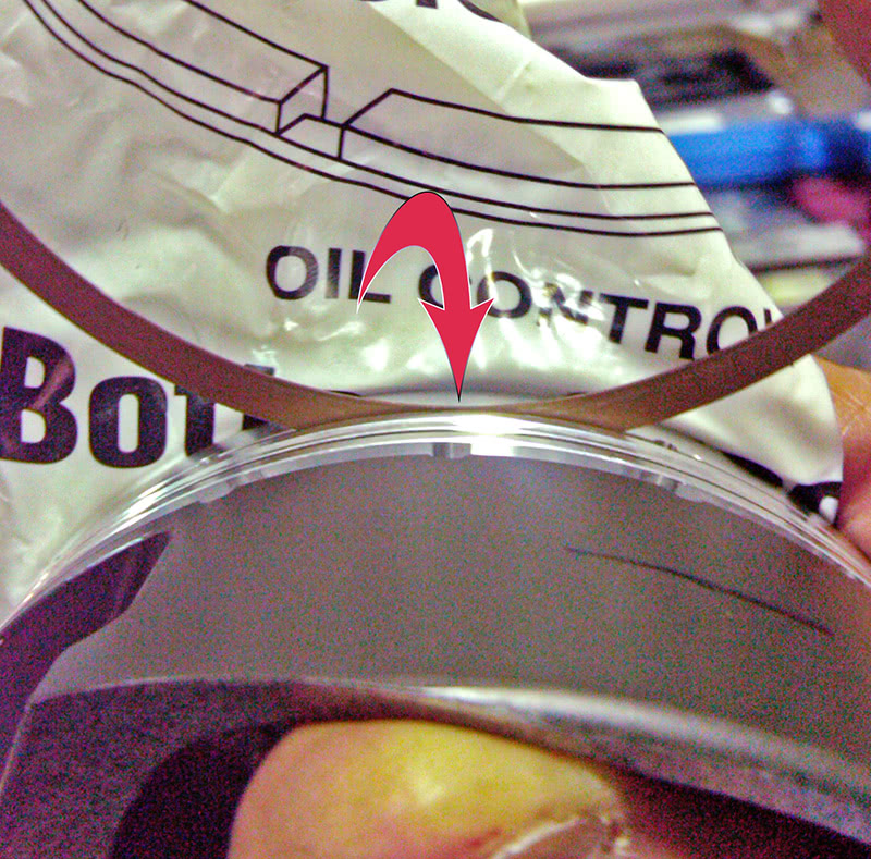
The first thing I spotted was that the intake wasn’t entirely sealed at the china rails. The thick layer of RTV was just a little short and you could see daylight from one end of the intake to the other. It needed to have rail extenders installed.
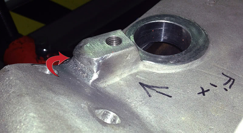
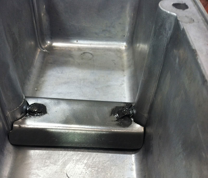
I also noted that the distributor could easily be turned by hand when the hold-down was fully tightened. While this was a crank-trigger engine, the distributor body was the spark sorter, and if left this loose it would rotate against the torque of the high-volume oil pump in the wet sump and start cross-firing other cylinders resulting in catastrophe. The intake manifold distributor mounting pad was too short for the tang opposite the distributor to react against and hold the distributor from turning. So, I fired up the TIG, welded it up and shaped it so that it would lock the distributor in place against the resistance of the oil pump.
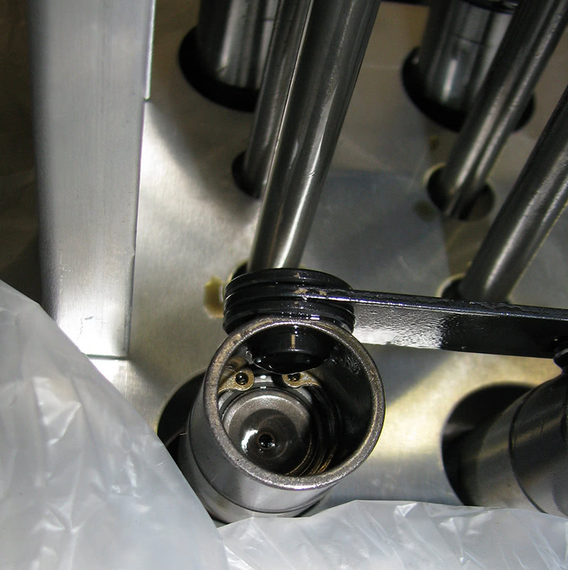
Further inspection revealed that the adjustable collar on the distributor body (an MSD billet piece) was not in the right spot, and the oil crossover channel at the back of the block sealed by the distributor body was nearly blocked off. Getting it in the right place (you have to remove the rear oil galley plug to visually center it) required that the distributor drive gear be machined a bit shorter and that the shoulder below the gear be reduced in diameter so it would drop deeper into the block. The block he was using was an aftermarket piece with a bulge that pushed over into the same place the distributor gear would normally occupy, and it was easier to modify the distributor gear than it was to modify the block.
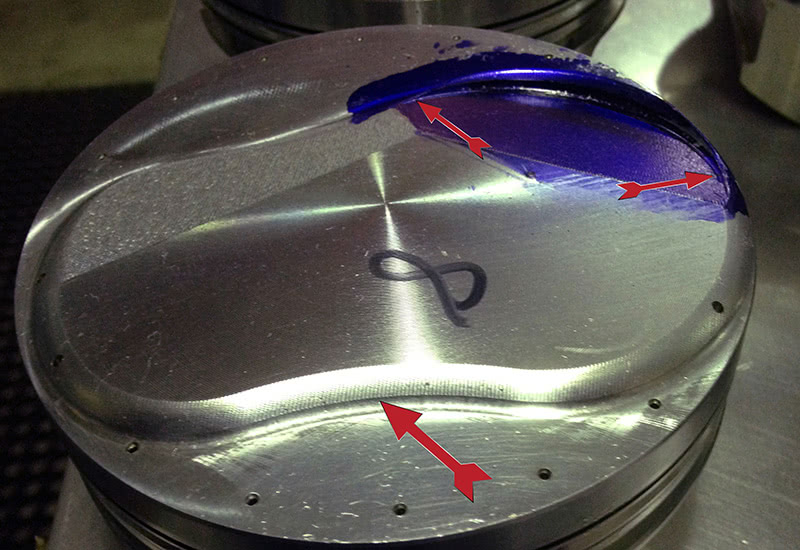
On the preliminary inspection, I noted a slight catch in the engine as I rolled it over. When I pulled the heads, I found that the intake valves were hitting the pistons — there was insufficient valve drop clearance AND radial clearance. The new pistons also arrived with too much dome on them to be used as supplied with his 12-degree aftermarket racing heads. The static compression calculated out to over 17:1 (diesel territory), and that, combined with the new cam’s early intake closing, resulted in a dynamic compression of almost 12:1! Since the upper limit is about 9.5:1 on racing gas, it’s a good thing he never throttled it up. It would have been an aluminum-scorching machine for sure.
As I unloaded the rods and pistons, I used my rod bolt stretch tool to measure how much stretch was on the rod bolts. I was stunned to find several bolts that had relaxed by .007-.009 in! The spec for the bolts was .0054-.0058 in. Turns out the owner “chased the stretch†as he tightened the rod bolts… a fairly common error it seems because I’ve heard of others doing this as well.
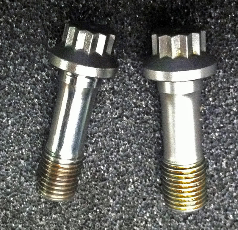
When you stretch bolts, you must lube them, turn them one time all the way to the final reading, and measure. If they don’t reach stretch you must loosen them all the way, re-lube the area under the head, verify that they have not taken a permanent stretch and then stretch them again in one motion, and measure them again. You must NEVER tighten them, take a reading, then tighten them some more, and read them again and so on. All you’ll end up doing is “chasing the stretch†and ruining the bolts. Plus, once over 75 ft. lbs. or so the head of the bolt and the shank above the threads winds up ahead of any thread movement and you’ll introduce all kinds of stress into the bolt doing it that way. The best way I’ve found to tighten racing rod bolts is the “torque and turn” method used on a lot of late model car fasteners. I tossed the old bolts and bought new ones.
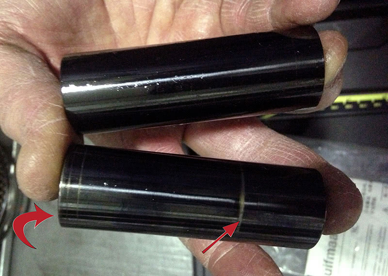
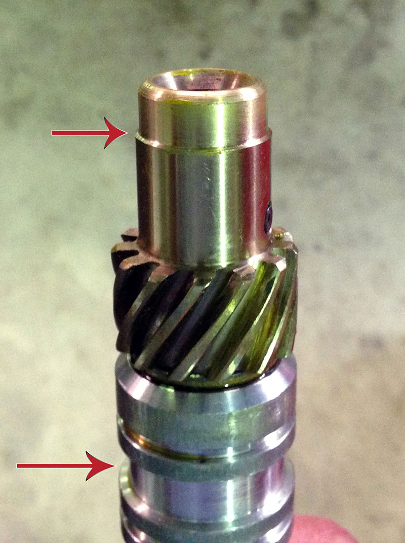
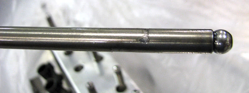
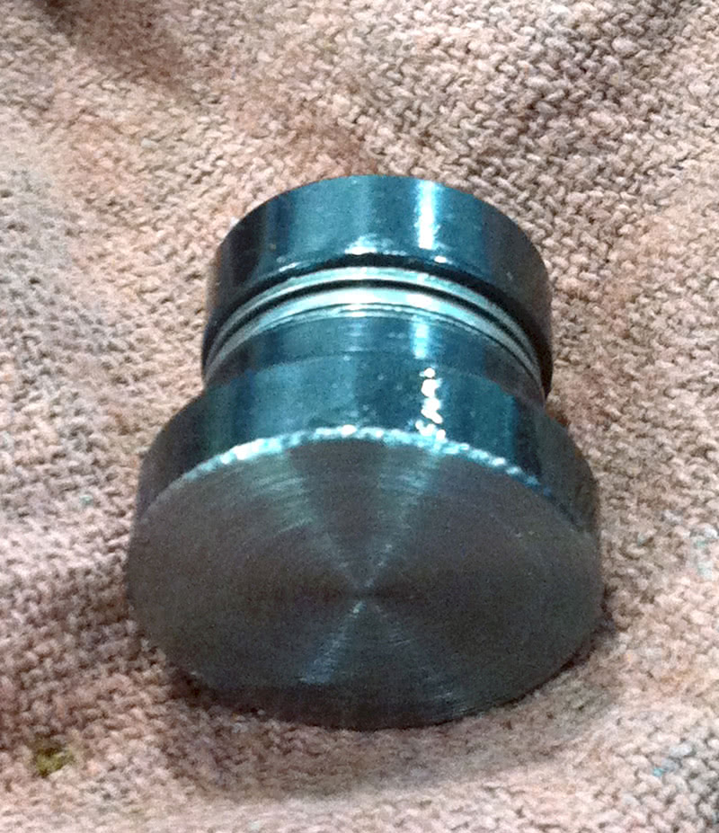
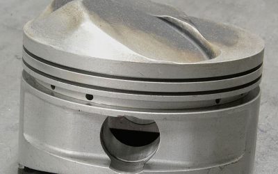
As I continued, I discovered that the DLC pins (Diamond-Like Coating — the black finish you see in the picture) was marred. It turned out that the pin clearance was much too tight. If you look closely at the lower pin, you’ll see that it is “faceted†from being overly tight in the bore. Both the rods and the pistons were resized to correct the condition.
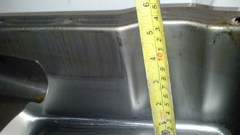
In my search for the low oil pressure problem, I discovered one thing early on: The oil pump pickup was damn near sitting on the floor of the oil pan. It was literally off the floor by just the thickness of the oil pan gasket, roughly .060 in. The oil pickup was modified to raise it up to just over 3/8 in.
The results? He’s been out with the car and he’s running about 177 mph through the traps — about 10 mph better than he’d done previously, and it was all done with his old combination. Now, he’s holding 70 psi of oil pressure all the way. I didn’t even have to use his new pistons or new camshaft to get him there.
The Third Victim: A 1970 Corvette, 350/350 horsepower, 11:1, recent rebuild, upfitted with a big thumping hydraulic roller cam
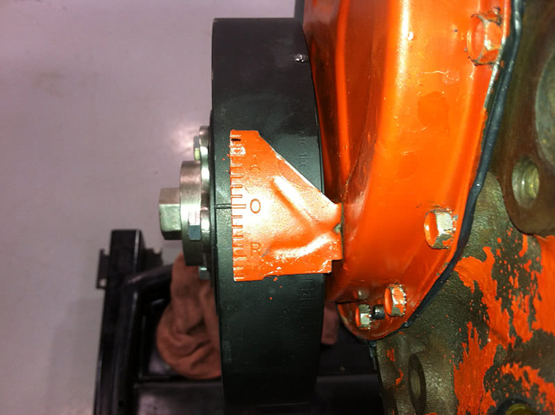
This classic arrived a very unhappy car. The owner reported that it wouldn’t idle below 1,300-1,400 rpm, it was using oil, there was some upper engine ticking, and it didn’t like it if you dropped the initial timing back to anything under about 25 deg. BTDC. The first thing I did was I stare at it a while. It certainly had a cam in it… diagnosis was complicated by how choppily the engine ran. So, first things first, I checked the original damper. It had slipped, but only by about five degrees (so far!). I popped the valve covers off and noted that on one cylinder there was a lot of thread showing above the aftermarket stainless steel rocker arm. Not a good sign. Flipping the aftermarket valve covers over, I noted that there wasn’t a baffle in sight over the PCV valve. Also, I had noticed when I drove it into the shop that it was running about 70 psi of oil pressure when it was hot. Hmmm…. I’m betting a high-volume oil pump right about now. The plugs were oil fouled even though it had only been a few thousand miles since the overhaul. I could see the positive-style valve guide seals through the springs, which made that path into the fire unlikely. So, I pulled the PCV hose off and — surprise! — it was full of oil.
The compression test told me I was in trouble — I had about 40 psi more down one side of the engine than the other! Now I’m in “what the hell is going on here?” mode. So, I called the customer for permission to pull the engine out for a better look.
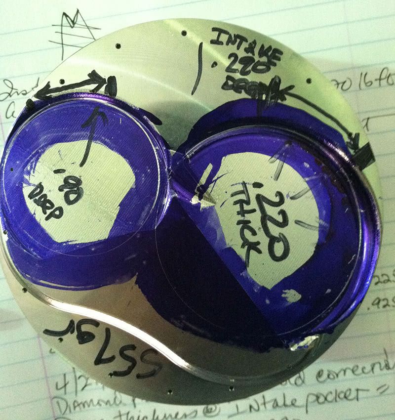
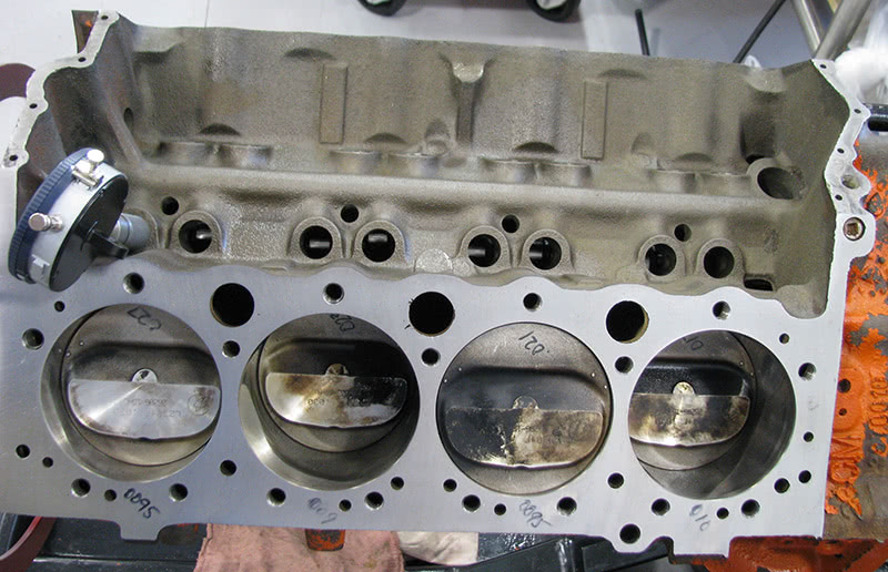
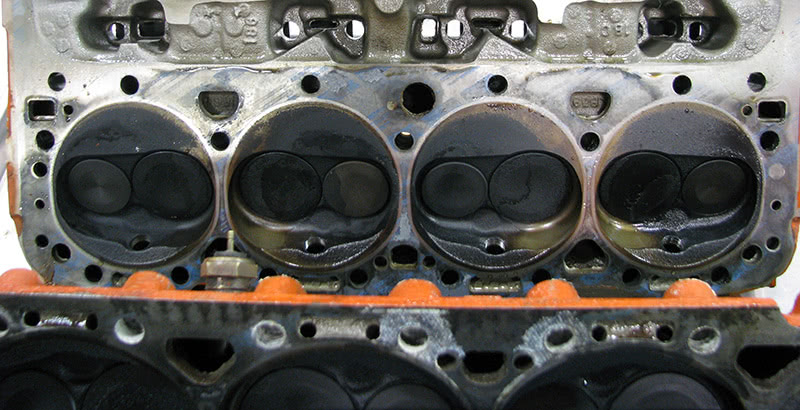
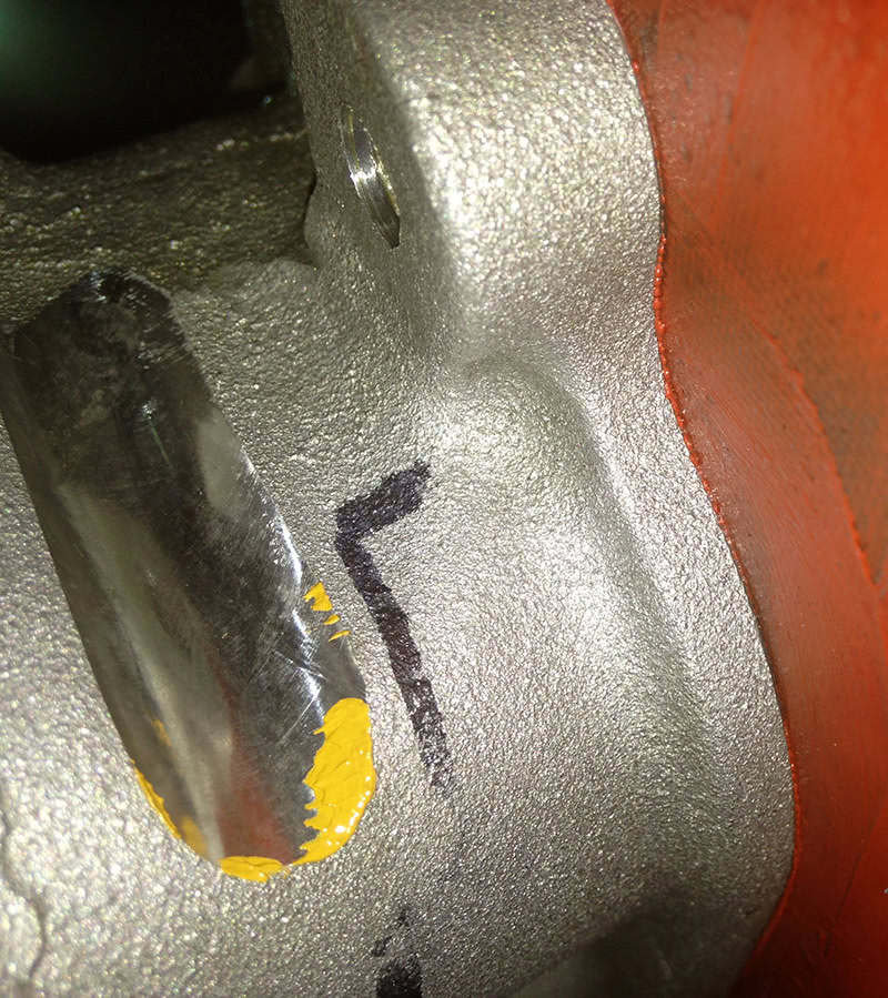
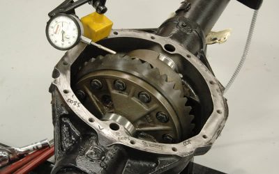
The pictures tell most of the tale. They had bored the block, installed the cam, roller lifters, stainless steel roller rockers and put it back together. Nothing fancy going on here… just gaskets and a few parts. It was originally an 11:1 engine, and that’s just how it went back together. If you look closely, you’ll see the original piston recession numbers on the pistons and the new recession numbers on the deck of the block (after I had it decked to fix it). This thing went from .019 to .027 in. from back to front on the driver’s side, and from .034 to .039 on the passenger side. The deck was tapered on one side, plus I had .020 in. difference in the piston-to-deck measurement. To make matters worse, the side with the sunken pistons had the cylinder head with the bigger combustion chambers — something like three ccs bigger. I had one side of the engine at about 9.8:1, and the other side at about 10.4:1. Okay, combine that with a big old lumpy camshaft and I guess it might not run so well. The thing that struck me was that all of this mess had to come from the factory this way! The engine was original and had only been freshened up this one time. Good old days indeed…
It had a high-volume oil pump, which I replaced with the original high-pressure pump. I wanted to try to keep some oil out of the valve covers. I also fabricated baffles to divert the oil away from the PCV valve. I discovered that a couple of pushrods were trying to shove their way out of the pocket in the rocker arms because the guide plates weren’t clearanced for the additional lift of the new cam. I also found one lifter fully collapsed and stuck down. He said he had a hard time getting one to quiet down and he had to keep adjusting it. Sigh.
Another thing I found was that the customer had removed and rebuilt the distributor, and didn’t get the gear on right. If you look at an old stock small-block Chevy, you’ll see a drill mark on the gear (check the picture) that must align with the tang on the rotor. Not a big deal, but still… There are 13 teeth on that gear, and you’ll throw your rotor register off if you mount the gear backwards.
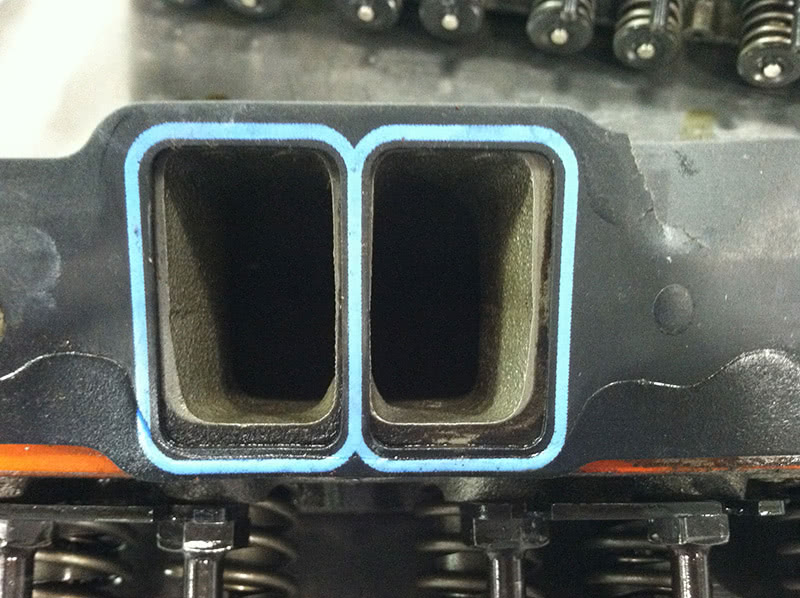
I also found that the owner picked the wrong intake gasket. It wasn’t leaking that I could tell, but it looked to me like it was only one good cold morning backfire away from whistling. There was also a cam button installed to keep the cam from walking in and out of the block and it was jammed up against the front cover so hard it was trying to bore its way through. A little lathe work to shorten it up and I set the end play at about .006 in. and it was good to go.
Most of the assembly looked pretty good — the rings, bearings and pistons were fine — and it looked like they did a good job keeping everything clean during the build. Once it was back together, it actually ran much better than I thought it would. It ended up back up to a true 11:1 compression ratio, and with 230 pounds of compression on all cylinders it does need racing fuel to run, but it will drop right down to 750 rpm and 10 degrees of initial timing, and just pop them off with just enough chop to remind you of why you love those dirty old cars. The oil consumption dropped to next to nothing and the old girl ran out pretty strong when you got on her. As an added bonus, my machine shop gave me the award for “Most Screwed Up Stock Block We’ve Ever Seen.†The wife and kids are so proud…
Myriad Ways to Mess Up
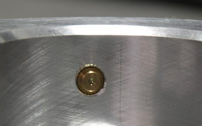
There are a hundred things to consider when doing this work, from parts that aren’t made right, to cleaning, and learning good measurement techniques. If you need an example of parts that cost a lot of money, but aren’t made quite right just look at the picture of the piston and ring. You can see that the ring stands proud of the ring groove… not enough back clearance. Oh, it’ll fit into the bore, but if you miss a problem like this on inspection, as soon as the engine starts and the ring heats up it’ll grab the cylinder wall and stall the engine… and then restart, stall, restart, stall, restart, and stall over and over until you finally find it. Install bolts that are too long in the water pump of some engines and you’ll shove the cylinder wall over into the piston. Fail to check your fasteners for proper minimum thread engagement and risk total failure. Or, fail to clean all threads on all fasteners and in all holes and risk false torque readings that leave a critical component so loose it’ll fall off halfway through the race. It’s all part of the many, many things you have to keep track of as you build performance engines.
The best part about this job is that there are always, always, always new things to learn every day. I learn something new on every engine, every time on every project… and that’s what keeps it fun.
Great Article, I’ve been in this trade over 40 years..and I too sometimes just shake my head on some of the things I see. For at least 25 of those years, I ran a Corvette specialty shop, and I can’t tell you how many times I had Vetts come into the shop running awfull, after they had got their car back from a “scheduled” tune up elsewere..The complaint would be rough idle,stalling,backfire on accel..etc.After taking the thing back a few times..with no success..it would land at my shop. After listing to the customer,and the engine..I’d take a look at the distributor hold down,notice how much the dist. had been moved..then I’d rotate it back to its original position,turn back the idle screw(they had adjusted)..and presto..the Corvette was a Corvette again! I’v probably Diagnosed 50 slipped balancers over the years..and it always amazes me how a skilled mechanic, during a regular tune up…would have to RETARD the timing and not question why!
I do have a question, why does the position of the dist. drive gear have any bearing on the drivabilty?..the gear turns the shaft and rotor..but the ignition timing at the plug is based on the relationship of the rotor& cap..I mean you can drop the distributor in the hole anywhere,index #1 wire at tdc, run the engine and adjust with light(with a good damper)! With the exception of Corvette’s with the tach drive cable..orientation of the housing/gear means nothing….later model EFI w/camsensor in dist as well)
non the less..great reading!!
The timing at the plug is actually set by changing the relationship of the distributor housing (stationary element) to the point cam or mag pulse generator teeth (rotating elements.) The cap is keyed to the stationary element, the housing, so the insert in the cap at each spark plug wire moves as you rotate the housing in relation to the rotor, which moves with the rotating member and with mechanical advance. Ideally, on an old Chevy points system, you’d like the leading edge of the rotor tip just overlapping at the trailing edge of the cap insert (clockwise rotation) at idle, no advance. As you speed up the engine the distributor shaft moves clockwise as the mechanical advance weights spring out.. and the rotor tip which is keyed to the distributor shaft also moves clockwise thus moving the rotor tip more into alignment with the cap insert. This alignment is called “rotor register” and is separate from the timing of the engine. Vacuum advance doesn’t affect the physical relationship like mechanical timing does, because the vacuum advance moves the breakerplate opposite rotation. But it will move the moment of arc strike counterclockwise again. Mounting the gear backwards can cause rotor register issues… the rotor may be so far away from the correct insert that it cross fires over onto an adjacent insert. Not always, it depends on how much mechanical advance you have, but it can happen. On race engines with spark sorters we always align the rotor tip with the cap insert at full advance just to avoid crossfire. If you want to observe this register movement first hand, take an old cap and cut a window in it and use your timing light to freeze the rotor motion through the window, just attach the light to a cylinder insert that lies directly in the window. Note where the rotor tip is as you rev the engine, with and without vacuum advance. If you’re like me there’s nothing like “seeing it” to make it easier to understand! Best, Greg
very informative and ive been building for many years