
This series is as hands-on as possible, and informs you of subtleties you just won’t find anywhere else.

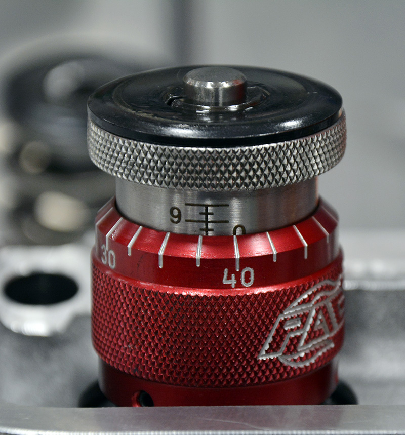
Never assume that you are accurately measuring anything unless you’ve got standards to use for calibration. I want to know if my spring height micrometer is accurate. It should be close, but how close is it? At 20 threads per in., each turn of the body should be .050 in., so I set up my height gauge on a small granite surface plate and zero the gauge on the plate surface. I then raise it and lower it a few times to confirm that it returns to zero.
Valve springs are among the most underappreciated, misunderstood, critical, and delicate components in the entire racing engine. They are primary contributors to the horsepower chain. They run astoundingly hot due to internal and external friction (plus some conductive heat from the combustion process through the head and valve stem), they cycle between 15 and 90 times per second, plus they bounce, surge, rotate, and rub against one another. All that makes them prone to failures that can result in the kind of engine catastrophes that are sure to make You Tube under the “biggest engine fails ever†category. In fact, I’d bet that most of the engine blow-ups you see are precipitated by failed valve springs.

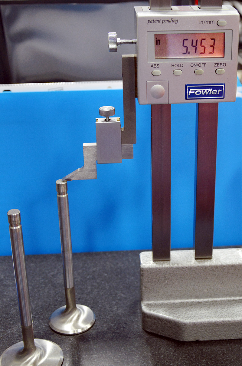
Next, using a two-in. certified standard I check to see that the height gauge reads out two in. — and it does.
Selecting the right spring is critical to the performance, longevity, and power output you can expect from an engine. They are easily overlooked and often go undiagnosed as a source of lost horsepower. The purpose of a valve spring is to preload the valve on the seat and (by extension through the rocker and pushrod) the lifter on the cam face. What you need to be able to do is control these parts so that the lifter can accurately track the camshaft lobe profile. The valve must accurately open and close at the designed points and follow the camshaft ramp to full close without bouncing off the seat. Bounce is a bad thing. Although some exists in nearly all spring-loaded poppet valve systems, it must be minimized to prevent seat, lock, retainer, and valve damage and a loss of accurate valve timing. We know that accurate valve timing is critical — some racing organizations spend millions on cams, often changing specifications just a degree at a time to arrive at the optimum cylinder filling and emptying event timing for a given application. If you can’t control when the valve seats and seals the cylinder, what’s the point? You’re chasing horsepower ghosts if you can’t control precisely when the cylinder seals and unseals. It doesn’t do much good to degree-in a cam if the valve train doesn’t follow the profile, does it?

Once I’ve checked the height mic, I change its reading a few times, reset it to two in., and recheck it. Now I know it’s accurate and repeatable and I can certify it for use. This particular one is supplied by PAC Springs, and the quality of the tool is exactly the kind of quality you see in the company’s springs.
Too Much is Just Right
How much spring pressure is enough spring pressure? The cam grinders often offer up a suggested pressure and rpm range for a cam and spring package. But those suggestions are pretty generic and they assume a few things. First of all, what kind of valve are they assuming that you’re running? Stainless steel? Sodium filled?  Hollow stem? 5MM stem or 3/8 stem? Titanium? So what assumptions do cam grinders make when they offer you a spring package? I certainly don’t know, but the suggestions are just that — suggestions. If you’re running conical or beehives, ovate wire, small-stemmed titanium valves and titanium retainers, you can use less pressure because the self-damping action of conical springs, beehive springs, and ovate wire springs means better valve control with less pressure. Obviously, lighter components require less pressure to be controlled, but if you’re running big, heavy stainless steel valves you’ll need to run the seating pressure up to control the mass. As a side benefit, changing valve train mass changes spring requirements in part because changing mass changes the resonant frequency of a system; mass helps you tune in and out of resonance, acting as half of the spring pressure/mass equation that dictates at what rpm resonance affects operation.
You would like to hit the design criteria on the nose, of course, but if you have to err, err on the side of too much pressure. While increased spring pressure does increase turning force and friction (it can account for as much as 30% of total engine friction, number three on the list behind the coolant pump and oil pump) as one spring is compressed, you have to remember that somewhere on that engine another spring is uncompressing and putting energy back into the assembly — which you already know if you’ve ever lost control of a break-over bar while rotating a race engine with stout valve springs on it. All I’ll say is if you’re going to be careless while you’re hanging onto that bar, you need to invest in an athletic cup, a mouth guard, and a full-face helmet because I’m telling you that a 30 in. bar will knock you stupid. Please don’t ask me how I know that — there are some things a man just doesn’t need to relive. The point is that you must control the valve or risk losing significant power, even at the expense of a little additional friction from excessive valve spring pressures.
Now I know that there are those who believe that high pressures will pull the heads off the valves or pound the seats out, but that’s not true. Race valves aren’t two-piece with the head and stem formed separately like valves were in the bad old days, and once at rest on the seat total load on the valve is not that high. Worn guides, LOW spring pressures and poorly designed cam profiles cause those problems, not high spring pressures. Think about it: Rumor has it that some Pro Stock guys are running titanium valves with 5mm stems, seat pressures well over 400 lbs., and open pressures over 1,200 lbs. Do you have to maintain those systems? Hell yes, but maintenance is three-quarters of the racing game anyway, isn’t it?
Common Valve Spring Terms and DefinitionsFree height Installed height Coil bind Open height Seat or open pressure Nose or open pressure Spring rate Spring rating |
 Intake installed height |
 Exhaust installed height |
 Valve seat height check |
 Intake valve stem height |
 Exhaust valve stem height |
 Autozero and then measure tip height |
| This intake valve measured 2.035 in. and is different from the exhaust at 1.9875. So why is this so common and what causes it? You’ll only know if you do quite a bit of measuring the first time you lay hands on your new parts, which I do just to see if all the work that was done to the heads was consistent. I start by measuring the stem heights of all the valves and seeing how consistent they are. In this case, there’s only a .003 in. difference between the intakes and exhausts. Since I’m set up, next I measure the valve tip length, since that will affect where the locks engage the retainer. Simply zero the height gauge on the top of the stem and drop it down to measure the tip. In this case, it’s a 3/8th in. tip and it measures .374 — within .001in. Next, I’ll measure the valve seat height by laying the head down on a flat aluminum plate and dropping a transfer punch down through to guide so that it rests on the plate under the head. I then set up to measure between the plate surface and the spring perch surface and zero out the indicator. On these heads, there was only a couple of thousandths of variation across 16 seats. Next, I measure the retainers and the valve spring seat locator cups (frankly, they are nearly always right on the money one to another), and that only leaves one thing:  the depth of the seat and how precisely the face of the valve was finished to get the overall installed height of the springs. Now, I can tell how accurate the seat-cutting equipment was. On this example, it was nearly perfect. The maximum installed heights on eight intakes ranged between 2.035 in. and 2.050 in., and the installed heights on the exhausts measured between 1.985 in. and 1.995in. In the end, the springs were installed at 1.970 to 1.975in. to get the seat pressure and distance to bind where I wanted it. Why is all this important (other than for satisfying my overwhelming perfectionist tendencies)? Two reasons: First, as things wear it tells you what you need to check and what things you can say with near complete certainty will not need checking — it helps you find problems more quickly. Second, the entire valve train (less the spring) is now a known quantity. | |
Spring preparation

All springs are subject to sudden failure, but most will give some kind of warning, slowly losing pressure over time. This Buxton on-head valve spring tester is the Cadillac of all spring testers and displays the kind of accuracy and repeatability that a serious racer needs to keep track of spring life.
Everyone approaches a problem differently, and I’m sure that there are many serious and capable engine builders out there who will not agree with the steps that I use to prepare a racing engine spring. I’m also sure that as time passes my rituals will change as I learn more and have more time to gather data. If there’s a really sharp championship builder out there willing to mentor me and set me straight on my process, I’ll just say “thank you†in advance. I’m a work in progress and I appreciate and accept all the help I can get.
I start with a physical inspection when the parts arrive, checking for nicks, scratches, and any signs of rust. Then, I cycle the springs five times to solid (bind) and take note of the pressures after the last cycle. I know that binding the spring lowers the pressure but I want that spring stabilized to the extent that I can get it stabilized. I don’t care if the pressure drops a bit — I can shim it to get it where I need it to be. In fact, installed heights as supplied by the manufacturers are only suggestions. As long as you’ve got the room, you can make the installed height whatever you need it to be to get the seat pressures you’re looking for. Ideally, you would like to see the spring fully compressed at full lift with just .030-.060 in. clearance from bind because approaching bind helps dampen spring oscillation and surge for the same reason that you can’t dance in a crowed elevator — no room to wiggle!
Next, I deburr the ends because I don’t want them to dig into the retainer or spring seat and remove bits of metal that circulate in the engine, especially titanium from the retainers, which is non-magnetic and much harder than the cylinder wall and crankshaft, thus prone to causing galling with dissimilar materials.
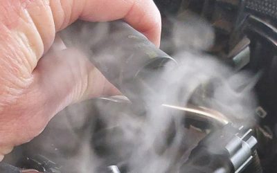
I then chamfer the inside of the top and bottom coils for stress relief. The flat ends are ground onto the spring leaving a relatively sharp inner edge. I use a chamfering cone to break that sharp edge. Next comes 24 hours in a vibratory polisher with walnut shells and a metal polishing compound to polish and provide a little stress relief. After a thorough cleaning in mineral spirits (you do NOT need walnut shells in the engine — check the ends where the tight wrap forms the flat top and bottom for remnants stuck between coils) I lubricate the springs with oil and set them aside for a second inspection.
 Pencil grinder and chamfered and radiused spring   Manley tool for chamfering the springs  Smooth enough not to catch |
 Must not nick the spring while grinding   Polished deburred and chamfered |
|
| Spring preparation is some of the most tedious engine work, in my opinion. I start by removing the sharp tangs and edges on both ends of every spring. I lay the end of the last coil back so that it won’t grab either the spring seat or the retainer face. I use a thin piece of aluminum and a plastic carpenter’s shim (available at Menard’s or Lowe’s) to protect the spring from an unexpected nick as I work. My goal is to minimize the amount of “digging” that those sharp ends do as the spring moves or rotates. If you look at a spring closely, you’ll see that as you compress it the coils try to roll, which imparts movement into the spring — on some engines at certain rpms, the spring can rotate completely around at a fairly high rate. I don’t want this little rotating shrapnel generator to remove material from the seat, the retainer, or the spring itself to share with other moving parts. Next, using the Manley tool shown I relieve the sharp edge on the inside of both end coils. Sharp is bad, radii are good. Then it goes in for polishing. When that’s done, the spring is bright, shiny, deburred, and radiused, and if you push it into your hand and twist it (clockwise in this example) it should not grab or cut your palm. |  | |
 Before and after polish   After polishing cleaning and oiling |
 The polishing rig is a repurposed cartridge tumbler   I like to tumble polish for twenty four hours |
|
| It’s pretty obvious in these pictures what polishing accomplishes. The surfaces are almost silky smooth after twenty-four hours in the media. You see those flat-wound dampeners? On these two-spring sets that dampener acts like a soft coupler between the inner and outer coil. That little friction coupler acts to “share” resonance between springs, adding just a little mass to its larger or smaller partner and/or grabbing and slowing the companion spring as it moves out of time to its partner. Since the individual springs go in and out of resonance at different rpm, the dampener couples them up to tamp down surge or oscillation. On three-spring sets, the close fit of the springs one inside the other does the same job. The takeaway here is that you should find it difficult to remove and install the inner springs… it’s how they’re designed. I’ll warn you about something here: When you grab the large outer spring to push the inners through, do not let the fleshy palm of your hand get in between the coils to where the inner coil you are pushing can pinch it between the outer-side of the inner coil and the inside of the outer coil. Acts just like a guillotine — you will bleed and cuss. Wear gloves. Don’t ask me how I know this. |  | |
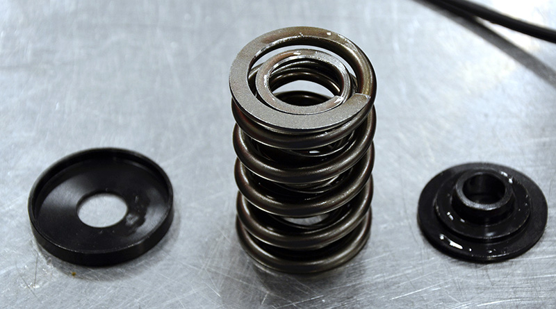 The entire spring package |
||
 Seats are part of the installed height |
 Buxton calibration spring |
|
 The Buxton is best for spring sorting and balancing |
||
 Precision gauge makes balancing easy |
 The spring seat on aluminum heads |
|
 Spring layout graph plus or minus seven pounds |
||
| After polishing, deburring, binding, and cleaning I like to lay out a balancing grid on a large piece of paper. The Buxton manual spring compressor is dead accurate and fast for sorting and laying out springs. Again, you need to use standards to verify your equipment calibration — when the equipment comes out, so does the calibration spring. It goes without saying that this is one spring you DO NOT want to take to bind! Two or three readings across the range will tell you if your tester is still in calibration. I sort springs individually and take them to an arbitrary height, then lock the travel on the ram to attain the same height each time and record the pressures. I then put the lower outers with the higher inners and try to get the entire batch within plus or minus 10 lbs. In this example, we are plus or minus seven lbs. across 16 springs. You’ll note that I’m holding a couple of different kinds of spring locators or spring seats, an inexpensive stamped piece and a CNC machined part from Manley. I’m not a fan of the stamped seats for any real performance work. |  | |
|
Once you measure the maximum installed height on your height micrometer, you can transfer the measurement to your spring tester just by moving the spring seat (or locator, if you prefer that nomenclature), spring, and retainer over to the tester platens and setting your zero. Compress to the installed height, lock down the ram stop, and run the set of 16, recording position as you go. Then, lower the ram to the maximum lift point, lock the ram, and run the springs again to capture seat and open pressures. You must use the retainer when you test the springs — the inner coils are shorter than the outers and you need the steps in the retainer so that the coils all load up simultaneously. You also need to have the seat in place. The lower platen represents the machined seat area on the head. If you put a seat or shim against that surface it has to be in place during spring testing. On the Compu-spring system, you can enter the retainer thickness so it will correct for that thickness in its computations, but it has no way to know if there is a spring seat used with the spring under test. You must test with it sitting under the spring, against the lower platen.   Don’t make setup hard transfer measurement with height micrometer |
 Compuspring makes hard work easy   Cannot check springs without the retainer  With the compuspring you have a permanent record |
|
When it’s time to put it all together (after you’ve determined the best installed height, seat pressures, and coil bind distances), you should have a good way to control your assembly process. I use the tray shown (available at CVS Racing Products) as I build and as I tear down to keep track of everything. Once the new parts are assigned a position, I mark them and put them on the tray in the correct location. The springs are sitting on the seats and shims and the valve guide seals are inside the spring. Once it’s all laid out, it’s time to build. I use Ultra Gel on the seats and retainers, as well as under the lash caps during the build. It really seems to do a great job reducing start-up wear. If it’s in the valve train and metal touches metal, it gets a dab of Ultra Gel. Don’t forget those lash caps if you are running titanium valves without hardened inserts. The steel roller in the rocker must run against steel at the valve tip. Another Buxton tool has found a home in my toolbox: a spring compressor. It’s the best all-around spring compressor I’ve ever used, and like all the company’s stuff, it’s top quality. You might not like it the day you buy it, but you sure will every time you get it out to use it on a valve spring that looks like a mis-labeled chassis spring. 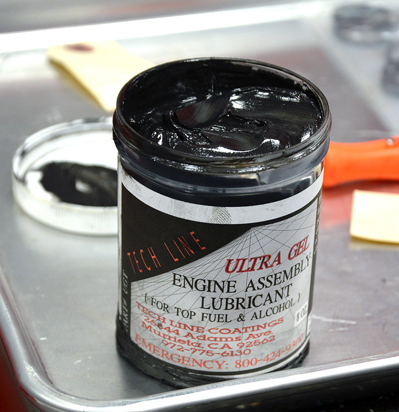 Use lube to prevent galling at retainer and spring seat  Valves springs seats shims retainers and locks storage  Titanium retainer and lash cap in place |
 There are many compressors buxton is by far the best   Buxton compression in operation  Loaded spring and valve tray 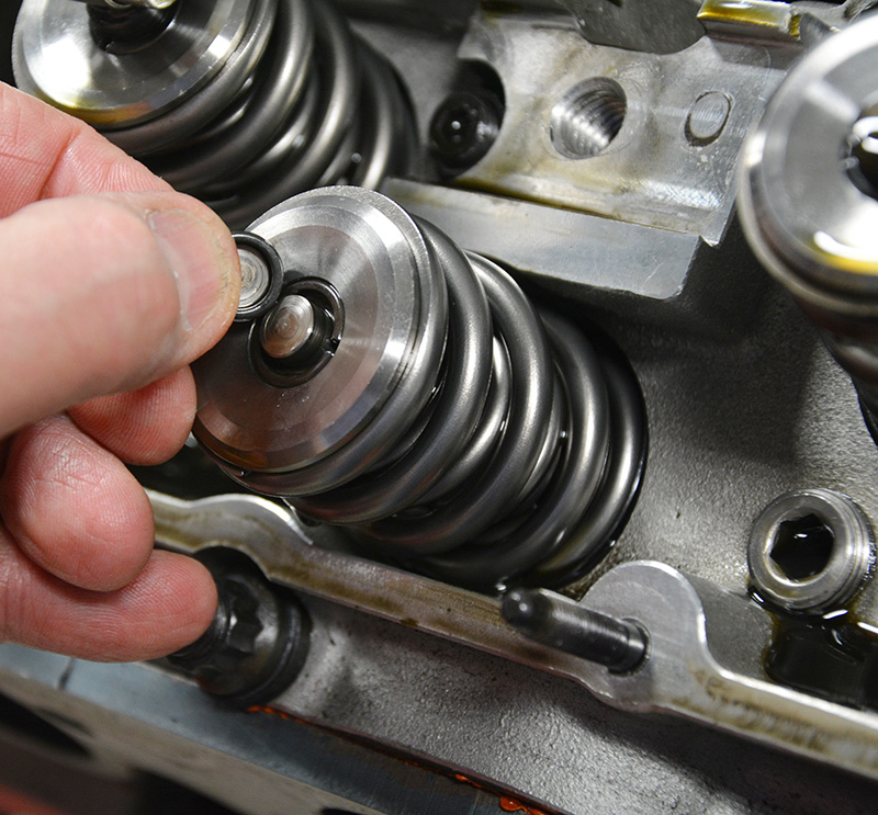 Have to use steel lash caps if there are no hardened inserts at valve tip |
I carefully and thoroughly inspect each spring a second time for nicks, pits, or scratches. The surface of spring wire is harder than Chinese arithmetic and it will fracture through any nick present. Next, I pressure check the inner and outer springs separately and sorted them — the highest and lowest are mated up and prepared for the final pressure check on the Compu-Spring tester. I swap the springs around as needed to arrive at installed pressures as close as possible across all springs.
Once installed and run, how often should you check springs? At least after each racing weekend, more if the event lasts several days. You should use an on-car spring checker that reads seat pressure, and you must inspect for rust and signs of end coil failures that might not affect engine performance very much. As a general rule, you should replace springs when you see your initial seat pressures drop by 10%. I wish I could tell you how long a prepped race spring will last, but I can’t. It seems that they either fail almost immediately (caused, I believe, by unseen stresses introduced into the wire during manufacturing), or they function quite a while, slowly losing pressure over sometimes as long as two or three seasons (on a 1,000+ hp Sportsman class racer).
 Now we are talking money titanium coated valve   Surface plate and stainless steel valves Controlling the valve is all about mass, preload, good components, good preparation, and proper assembly. If you’re running high dollar, small-diameter coated-stem titanium valves like the one shown, or big old heavy 3/8-stem stainless steel valves, you’ve got to size the support parts appropriately if you’re to have any hope of getting the valves to follow the cam lobes. Making power is all about precision and good design. |
Because they’re expensive and labor-intensive to prepare, getting a little extra life out of them saves time and money, so here are a few suggestions. Between race weekends, use a spring oil spray like Comp’s #106 product and replace any spring that rusts because those tiny pits are the starting points for most failures. Keeping your race car in a climate-controlled shop is the best practice, but keeping the spring lubed may be your only option. I’ve also heard of racers rolling the engine over by hand periodically or releasing the valve train in the off season, but I’ve got no way to evaluate the efficacy of that practice. We tear down every year for inspection, so for us that’s not an issue.
Other considerations
Other often-overlooked factors are the operation of the cam drive and the harmonic damper. Belt drives aren’t just for quick adjustment at the track (is there ever something “quick†at the track after you drop half the parts in the grass or roast your hand on a hot header? Factoring in search time and the drive to the hospital, you’re better off with good prep at the shop).
Belt drives absorb a lot of the violent snapping energy stored in the crankshaft as each power pulse hits, and it’s the same with the harmonic damper. Dampening the snap of the crank so that it doesn’t vary cam speed smoothes valve train operation and removes one more excitation force that can set up resonance.
On the output end of the crankshaft you’ve got quite a bit of mass in either a flywheel and clutch assembly or torque converter, but on the forward end you’ve only got the damper, plus maybe a drive for an alternator, vacuum pump, and dry sump oil pump. The cam belt drive and damper are key components in stabilizing valve train action and producing smooth and repeatable valve motion on any cam-in-block “V†engine.
Â
Resources:
PAC racing springs https://www.racingsprings.com/
PSI springs https://www.psisprings.com/
Isky homepage https://www.iskycams.com/
Lunati https://www.lunatipower.com/Category.aspx?id=23
Comp Cams https://www.compcams.com/Products/CC-‘Valve%20Springs%20By%20Usage’-0.aspx
FerreaÂ
Manley https://www.manleyperformance.com/
CraneÂ
Spintron video showing high speed valve spring operation https://www.youtube.com/watch?v=yfmb-tCo2yA
Â

Thank you very much!!
Thanks for an excellent article! I recently purchased a media tumbler and trying to polish a set of springs. I am using the walnut shells but I am curious as to what polishing agent you use and what the blend ratio would be.
Thanks, Randy
Hi Randy,
Thanks for your comment. We spoke with our technical editor, Greg, and here’s what he has to say:
Hope that helps.