

Our man Greg gives us science, geometry, and subtleties most of us have never even considered.

This set of Iskendarian solid lifters features a heavy-duty Marathon bushing style bearing in place of the typical needle bearing used by most lifter manufacturers. They are completely rebuildable and very durable. We have gone as long as six seasons on a set, with valve spring seat pressures running around 325 lbs. and over-the-nose pressures of 850 lbs. Good solid product from an old and respected company.
There are only a few basic rules to engine performance, just a few places where improvements are needed to increase output and reliability. Of course, these few rules grow legs when you start considering all the possible combinations of parts. A few rules become thousands of iterations and that yield thousands of different results, some good, some not so good.
A good first step to increase performance is to begin by increasing the efficiency of the air pump by decreasing inlet and outlet restrictions and by maximizing cylinder head flow. Speeding up burn rates and creating a homogenous mixture with increased chamber turbulence is an absolute must. Friction should be reduced as much as practical — that’s a big one, and it’s largely free! Low-tension oil control rings, roller lifters and rockers, the lowest pressure valve springs that will meet your needs, and roller bearing cam bearings all come to mind. Air-fuel ratio and ignition timing have to be optimized for the application and the effects of the heat of combustion must be contained or controlled; in some cases by coatings and barriers, and in some cases by effective blocking and removal. Even the power losses associated with water and oil pumps have to be accounted for and minimized without compromising durability.
Speed

A whole valve train is often designed around heads with large and moved ports. On modern high-performance cylinder heads, it’s difficult to get the pushrod from the lifter to the rocker seat with the larger intake ports that are being developed. This Jesel rocker has a canted trunnion axle, an offset pushrod seat, and the tip that rides on the valve stem is bent at an angle to locate over the stem center. Plus, it’s just damned pretty work.
Since horsepower is directly related to engine speed, systems affected by or limited by speed must be re-engineered to live at higher speed and the static and dynamic compression ratios must be selected and tuned for best power at the designed speed. There are other considerations as well; both the inlet and exhaust conduits are violent, pulsing, erratic environments. In the exhaust, there are supersonic and subsonic waves and high- and low-pressure pulses that form ahead of and behind moving exhaust gas columns. If you think about it, it’s a miracle the damn thing even runs.

This is how a flat tappet rotates on its cam lobe, mitigating wear.
If you were forced to pick two spots where the most power increases can be gained — which is difficult because it’s really a system and a few good parts surrounded by a lot of bad parts makes for a poor result — you’d have to pick the cylinder head and the camshaft, probably in that order. While overhead cams dominate in many racing venues and in many production makes and models, the overhead valve cam-in-block remains the mainstay in many forms of American auto racing.
Complicated dynamics
Manipulating a valve through a cam, lifter, pushrod, and rocker system in a performance application is more complicated than it seems at first. There is a lot of linkage, mass, and dynamic interactions that aren’t apparent to the average engine builder. The entire valve train acts like a spring system, apart from the spring itself, which is a troublesome component just on its own. The whole system is prone to resonance, deflection, and surge, and the added difficulties introduced by high seat angles (up to 55 degrees) that wedge the valve into the seat, the high valve opening pressures with blown or nitrous applications and high spring pressures needed to control the valve side of the rocker at high rpm just add to the mix.
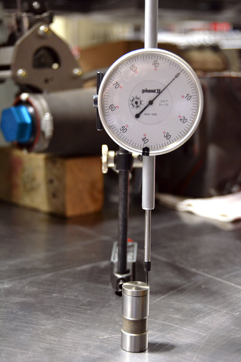
I laid this solid lifter against a straight edge to see if I could see the convex form on the bottom, and it was clearly evident. I later measured it and it was just under .002 in. on this lifter.
Cams and valve train systems engineering is advancing explosively as dynamic valve train testing systems (such as the Spintron) reveal exactly how much of what is needed to produce a valve train system capable of accurately translating the cam lobe to valve motion with the least amount of friction, deflection, and instability. As Billy Godbold of Comp Cams said, “After you put a strain gauge, load cell, proximity probe, or laser tracking system on every part in the valve train you really wind up rethinking all of your original assumptions. The cool part is that you gain the opportunity to make some really big design advancements. The process might be painful, but the benefits are real.†In other words, it does no good to have the best cam grinder in the world grind your cam if the lifter, pushrod, and rocker system can’t translate that lobe into full valve travel, at the right time relative to piston position in the cylinder, with no loss of control.
When it comes to lifters, there are a lot of choices. There’s flat hydraulic and solid both with and without EDM lobe oil feed holes, mushroom lifters (a smaller body with a larger foot, used on antiques and classics only these days), high leak rate lifters (like Rhoads), roller lifter hydraulic in both full travel and limited travel configurations, solid roller, link bar systems, dog bone systems, cassette systems (where roller lifter orientation is controlled by a cassette bolted into the lifter galley, mostly used in original equipment applications), keyed lifters, special long lifters for tall bores, tall and short seat height lifters, needle bearing supported roller axles made with both large and small diameter needles, bushed roller axles, large roller wheel options and even some cartridge lifter systems where the lifter and its supporting bore are bolted in as an assembly. If you want to start your education on valve train components, go to https://www.jesel.com/valvetrain/, download Dan Jesel’s catalog #11, and read all the notes and specifications you’ll see there. If you absorb it all, you’ll know more than a lot of guys out there racing.
 |
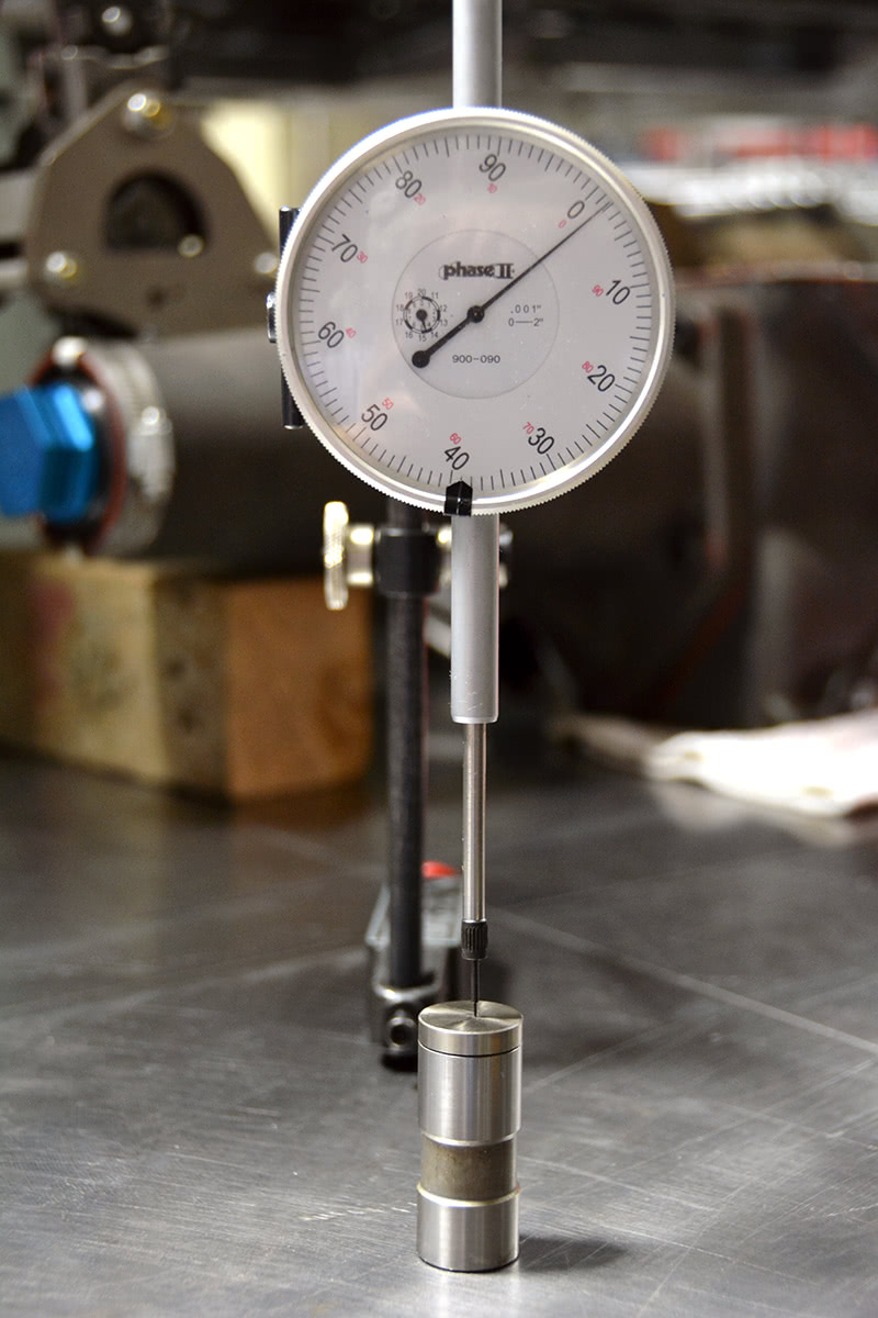 |
| I set the lifter and dial indicator up on a surface plate and measured the difference between the height at the crown and at the edge of the lifter. It measures right at .0018 of an inch. | |

This particular cam has a pretty good inverse ramp on both the opening and closing side of the lobe. If you look right at the arrow, you can see that there is a dip in the lobe face. You can also see the mark left by the wheel as it came off lash and engaged the lobe. This cam has a relatively small base circle with a fair amount of lift, so these ramps are used to help control the rate of acceleration.
Rollers ascendant
While there are good reasons to choose a flat tappet solid or hydraulic lifter cam these days — economy and a wide selection being two — those reasons are slowly being eroded by the proliferation of grinds available in roller cams by all the major manufacturers and by dramatically improved street roller lifter designs. Roller lifter durability is vastly improved, and keyed, cassette, dog bone, and linked roller systems give you a wide range of options for either the street or the racetrack. Basically, if you aren’t rule- or class-limited and if you’ve got the money to afford the upgrade, roller cams are the way to go.
 and is a keyed, low-seat roller lifter. It came out of an SB2 that had an unfortunate accident involving a piece of track debris that snapped the dry sump drive belt at 9,000 RPM. I guess that’s why it’s called “racing†and not “winning.â€")
This is an example of some of Dan Jesel’s work. This has a “diamond-like coating†(DLC) and is a keyed, low-seat roller lifter. It came out of an SB2 that had an unfortunate accident involving a piece of track debris that snapped the dry sump drive belt at 9,000 RPM. I guess that’s why it’s called “racing†and not “winning.â€
Every lifter type has its flaws, particularly if you’re dealing with a stock or near stock block where the diameter of the cam tunnel and cam bearings determine the cam core diameter and unmodified lifter bores determine the lifter diameter. Flat tappet cam designs are velocity limited; they are limited to how rapidly they can open the valve based on the cam base circle diameter and the lifter diameter. It’s a geometry problem: If you try to increase velocity beyond the physical limits you end up trying to knock the bottom of the lifter off rather than push it upward. If you can’t increase the rate of lift, the next question becomes how much total lift can you get because there is a fixed relationship between lift and duration if the velocity is the limiting factor. In general, lift can only rise at a rate of about .001-.002 in. per degree of duration with a flat lifter without exceeding velocity limits; to get the lift you need the duration must get longer to control velocity and at some point the duration becomes wrong for the application, or you’re stuck with poor idle quality, low engine vacuum, and a poor carb vacuum signal. As you can imagine, opening a valve much too early or closing it much too late, which is the natural result of excess duration, is officially “not good.â€
More lift is essentially “free†horsepower, particularly if you open the valve to the point where it is no longer the primary restriction in the inlet conduit. Well, okay, free insofar as negative impact on drivability and low-speed performance. You still have to design the valve train to control the valve. The point is that at some point the intake valve, normally the biggest problem in the inlet side, “disappears†and cylinder filling gets much, much better.

This roller cam has a larger base circle and the lobes don’t have inversion ramps. You can still see the pressure mark where the lifter wheel intersected the lobe. These forces actually cause a deformation of the parts involved with stress induced just below the surface of the lobe and roller wheel. Over time, these stresses can lead to cam lobe failures. Good lubrication and micro-polishing help.
Diameter and lift
As it so happens, there are some pretty good rules of thumb regarding the relationship of valve diameter to valve lift (courtesy of Billy Godbold of Comp Cams):
- For an old-school street and performance racer (from the ‘50s to the early ‘80s, perhaps) the lift should be 20-25% of the intake valve diameter.
- For a modern performance cam, the lift should be 25-30% of the intake valve diameter.
- Sportsman racer, 30-35%
- Competition and professional endurance racing, 35-38%
- Drag Race, heads-up competition, 38-44%
- Pro Stock 45-48%

The tiny EDM hole you see is there to promote oiling between the lobe and lifter foot and slow lobe wear when running valve spring pressures that are right up near the high limit for solid lifters. Once you get to about 450 psi over the nose, you can expect to see failures. Extra oil helps.
In other words, assuming a two-inch intake valve for all applications above, a street performance engine requires .500-.600 in. lift. The Sportsman racer will need .600-.700 in. lift, the endurance racer will require .700-.760 in., and the Pro Stocker will have to have .900-.960 lift. Of course, no Pro Stocker would run such a small valve, but you get the idea. Once you see that for a given engine in a given application there is a pretty specific amount of lift needed to optimize power for that application you can also see that getting there without having too much duration gets you to a roller cam application pretty quick. Can you get to high lift numbers with a flat tappet cam? Sure, with high rocker ratios and a lot of work, but you still have to remember that once you get past about 400 lbs. of over-the-nose spring pressures you’re going to start increasing friction and losing durability — nervous at 400 lbs. and failures at 450 lbs. is a good rule of thumb with flat lifters and spring pressures and as the lift gets higher the spring pressures go up with spring compression.
Flats facts

As you can see with this set of Comp solid rollers, there is a huge difference in pushrod seat height between this set and the Jesel. The Jesel lifter seat height is only about 1.190 in. as measured from the bottom of the wheel to the lowest part of the seat pocket. The Comps measure 2.150 in. — almost an inch higher. While this helps by giving us a shorter pushrod, it hurts because of angularity and lifter bore bushing wear.
Even if you spent a fortune on special surface preparation — nitriding, micropolishing and so on — and used the best oils and the best materials available, there is a limit to how small the nose radius of the cam lobe can be before Hertzian contact stresses overload the material and the lobe fails. There’s a point where making it work just doesn’t make financial sense unless you are rule- or sanctioning body-restricted. Now, if you’re talking about low lift, low duration cam designs and small cam tunnels, then the flat tappet cam may be the best option. That said, for those traditionalists that choose to use flat solid or flat hydraulic systems here are a few tips or things you might want to know:
- An engine with a larger cam core and a larger lifter bore is an advantage because it helps fix the geometry challenges and increases the velocity limit of a flat lifter. This is one case where bigger really is better. Actually, bigger is better for all lifter types — there are roller cores out there up to 82 mm (that’s just under three and a quarter inches!) and lifters sized up to 1.095 in. with rollers as large as 1.220 in. (the lifter bore is notched to fit the wheel diameter.)
-

Here is where stock cam tunnels and stock cam bearing sizes create an issue. You can see where the base circle is undercut in the photo. Obviously, this cam will not be a stiff as something built on a bigger core, and it will suffer deflection. This is not optimal for a performance application, but sometimes it’s all you have to work with.
As most of you probably know, in most instances you shouldn’t place a new flat lifter on a used flat cam. The reason for this is because the wear in patterns are unique to the lifter and lobe and putting a new lifter on an old lobe will very likely cause a cam lobe failure in short order. It’s not a guaranteed failure, but the odds are against you. The bottom of a new hydraulic or solid lifter is slightly convex, that is, bowed downward, by about .002 in. and the lobe of a flat solid or hydraulic cam is tapered — lower toward the front of the engine and higher toward the rear. This accomplishes two things. It pulls the cam slightly into the block so that the cam thrust surface on the cam sprocket is held lightly against the block or thrust plate and it makes the lifter spin so that it won’t rapidly wear through the lifter bottom.
- A new cam with a taper and a new lifter with a convex bottom have what amounts to a point contact when first installed, which is why you must use the correct assembly lube and why you must bring the engine rpm up over 2,000 for the first ten to twenty minutes of run time. It gives that point contact time for a controlled break in so that the point contact becomes wider and the unit pressure becomes manageable. Remember that a 350-lb. valve spring with a 1.8 to one rocker exerts 630 lbs. of pressure back against the cam lifter and all that pressure is exerted on a point about the size of a sharp pencil. Figure the unit pressure on that one once and now you understand why the correct lube and break in is critical. Running it up to 2,000-2,500 is critical because nearly all of the oil supplied to the cam/lifter interface comes from crank throw-off. Under 2,000 rpm, there isn’t enough oil pitched up onto the cam to keep the lobes and lifters alive during break-in. The lifter-to-lifter bore clearance should only be about .0015-.002 in., so it’s not going to get oil by leaking down from the lifter oil gallery —the clearances are too tight for that. That oil is mainly there to be pumped to the top of the engine to cool and lubricate the valve springs. There are instances where you might be able to run a new lifter on an old cam because not all engines rely on a tapered lobe and a convex bottomed lifter to create spin. Some engines offset the cam lobes relative to the lifter bore center line to cause the spin, and the lobe face and the lifter bottom are dead flat. Some of the older Chrysler engines and MG engines, for example. Just make sure you know how lifter spin is established before you try it.
- If you find yourself with a cam that is oversized for your application one option you may have heard of is the Rhoads or fast-bleed lifter. Most cam manufacturers see fast-bleed lifters as more of a crutch than as an optimized solution. If you don’t start with a clean sheet engine build, they may offer a patch, but we really want the duration to stay close to the same throughout the rpm range. Any time you reduce system stiffness, the duration will tail off (sometimes dramatically) as rpm and dynamic load increases. To be fair, the test results I’ve reviewed with Rhoads lifters indicate that they returned consistent results in increasing engine vacuum and taming low engine speed stability, but often resulted in lower torque and power levels. For someone who inherited a wild cam, they may offer a solution, but I’m not sure that I would ever build an engine with a fast-bleed system intentionally.

0 Comments