

Backpressure can seriously sabotage your efforts to get plenty of air into the cylinders, yet many people overlook it and don’t know how to detect its presence. And how is the MAF sensor affected?
Supporting technical input from Steve Zack, Technical Instructor for Bosch/OTC |
Some of the hardest-to-diagnosis engine performance problems with today’s modern computer-controlled, fuel-injected vehicles are caused by excessive exhaust backpressure (typically a plugged catalytic convertor) and incorrect data from the MAF (Mass Air Flow) sensor. An automotive PCM (Powertrain Control Module) is just like any other computer: It must have the correct inputs if it is to do its job properly. Or, as it often expressed in the computer world, “garbage in, garbage out.†The engine itself must be in good shape, and the data from each of its sensors must be accurate and within the operating specifications of the PCM, plus the exhaust system must allow the spent gases to flow out of the engine without restriction or performance will suffer. Since no engine will perform properly with restricted exhaust, one of the first things you should do when diagnosing a vehicle for low power and related problems is to check for excessive exhaust backpressure.
Exhaust Systems

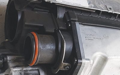
This backpressure test kit includes a gauge, drill, bung, installation tool, and adaptors that allow you to tap into the exhaust system and measure backpressure directly.
Today’s engines use a catalytic converter that contains platinum, palladium, and rhodium to create chemical reactions that convert the pollutants in the exhaust into less harmful elements. As the catalytic convertor ages, or if it is overheated by over-fueling due to misfire or incorrect air/fuel mixtures, it will often begin to restrict the flow of exhaust through it, which will cause a loss of performance. This can occur very quickly, or it can happen so gradually that the driver does not notice it until one day he or she realizes that the vehicle no longer has the same power that it had in the past.
Backpressure
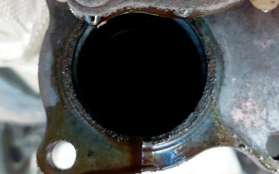
In order for any internal combustion engine to perform properly, the fuel and air mixture that is burned in the cylinders must be able freely flow out through the exhaust system. If this system becomes restricted, it will create excessive exhaust backpressure that will reduce power output and fuel economy, and also create misfiring. The first thing you should do if you suspect problems with the exhaust system is to look for mechanical damage (dents, crimps, or floating baffles), or corrosion (big flakes of rust). Then, it would also be a good idea to perform a “thump†test on the catalytic convertor, which involves hitting the convertor lightly with a rubber mallet. If you hear rattling, chances are the ceramic substrate has broken into pieces. The catalytic convertor can also “melt-down†or clog if it is overheated by being exposed to the exhaust from an engine that is operating on an excessively-rich air/fuel mixture, or an engine that has a misfire issue.

The operation of a catalytic converter seems like alchemy. The two-way oxidation type appeared 40 years ago, believe it or not (courtesy Walker).
When was the last time you used a vacuum gauge?
An easy, low-tech way to check for excessive backpressure is to use a vacuum gauge. This works because the vacuum produced by an engine is affected when the exhaust is strangled. The first test involves taking a vacuum reading at idle with the transmission in neutral, and taking a second reading at 2,500 rpm. The reading at 2,500 rpm should be slightly higher than that at idle, but if the reading decreases there’s a good chance that the exhaust system is restricted.
The second test involves running the engine at 2,000 rpm for three minutes, noting the vacuum reading, then momentarily snapping the throttle to wide open and allowing the rpm to return to the normal idle speed. The vacuum reading should drop to near zero when the throttle is snapped open. When the throttle closes suddenly, the vacuum should jump to slightly above what it was at 2,000 rpm, then it should return to the normal vacuum within three seconds. If it takes longer than that, exhaust flow is most likely restricted.
Checking with a scan tool
You can test for a restricted exhaust/plugged catalytic converter with an enhanced scan tool. On the Bosch/OTC Encore, for example, you can record and graph the MAP (Manifold Absolute Pressure) sensor voltage. The first step is to run the fully-warm engine at 2,000 rpm for three minutes and note what the MAP sensor voltage is — typically, it should be 1.2 to 1.6V. Then, snap the throttle to wide open and allow the engine to return to normal idle speed. The MAP signal will rise to approximately 3.8 to 4.2V, then should return to 1.2 to 1.6V in less than three seconds. If it takes longer than that, the catalytic converter may be plugged.
If the vehicle is not equipped with a MAP sensor, you can go to Global OBD II on the scan tool and select the Engine Calculated Load PID (Parameter ID), then with the engine at normal operating temperature and at idle, record Calculated Load (typically 20% to 40%). The next step is to speed the engine up to 2,000 rpm, then snap the throttle wide open (the Calculated Load will immediately climb to 100%). Once the throttle is returned to the closed position, the Calculated Load will drop to 0% and it should return to the previously noted idle reading in less than three seconds.
Direct pressure readings
The most direct method for testing for restricted exhaust is to check the actual pressure in the system with a gauge tapped into the system — you can read the real number of psi. The backpressure readings at idle on most engines should generally be less than 1.5 psi. General Motors recommends no more than 1.25 psi at idle and no more than 3 psi at 2,000 rpm with a unloaded engine. A partially-restricted exhaust system should flow enough exhaust at idle to allow normal running, but at higher engine speeds or when the engine is operated under load it will hurt engine performance; thus the need to rev and hold the engine at 2,000 rpm to check the backpressure.

A scan tool will let you see how well that MAF is operating. This one’s good.
A “good†reading on most engines at 2,000 rpm should be 3 psi or less. It is a good idea to observe what the backpressure reading does while you are holding engine speed at 2,000 rpm for a few minutes. If it remains steady, chances are there is no major restriction. But if the reading gradually increases, it means backpressure is building up and there may be a blockage. You may also want to rev the engine to 4,000 rpm to read the backpressure. Many stock exhaust systems will show readings up to 4 psi when the engine is operated under load, but if the reading is unusually high or it continues to climb at a steady rpm, it usually means there is a restriction in the exhaust.
What the MAF sensor does
Most modern fuel-injected engines use a MAF sensor so the computer can read the volume of air the engine is consuming, corrected for density. This data is an important part of the calculations it uses to determine the ignition spark timing and fuel injector pulse the engine should get for ideal performance. The PCM relies on accurate data from the MAF, along with that from the throttle position sensor, the engine speed sensor, and various other sensors to calculate the load the engine is operating under so it can command the duration of the fuel injector pulse, the ignition spark timing, and the transmission shift points. When the engine is operating in closed loop, the data from the oxygen or air/fuel ratio sensor is used by the PCM to fine-tune the blend to achieve maximum efficiency.
.")
Here are the most common converter failures, any one of which is likely to increase exhaust backpressure (courtesy Walker).
If the actual air flow into the engine does not match the output data the from MAF sensor, the PCM will not command the correct ignition spark timing or injector pulse width. This incorrect data can cause both hot- and cold-starting problems as well as hesitation, stalling, rough idle, and low power output. The PCM will adjust the air/fuel mixture by referencing the data from its O2 or AFR sensors, but when it has to correct mixture by more than 5% it will cause the PCM to perform at less than maximum efficiency. If incorrect data causes the PCM to command the spark timing to be too advanced, the PCM can reduce advance according to data from the knock sensor (if used), but if the spark timing is not advanced enough for the needs of the engine it will not perform as it should.
A scan tool can be used to observe the data the PCM is getting from the MAF sensor as well as that from all the other sensors it uses to allow a modern engine to perform properly. The problem:Â How do you know that the data the PCM is getting from the MAF sensor is accurate? The following charts show what a good and bad mass air flow sensor output readings look like when they are graphed on an enhanced scan tool such as the Bosch/OTC Encore.
Checking a MAF sensor for accuracy

This MAF is so far out of calibration that performance will suffer substantially, not to mention setting off the self-diagnostics.
Many Ford and General Motors PCMs have a calculated air-flow reading that can be referenced on an advanced scan tool and then compared to the output data reading from the MAF sensor on those vehicles. If you are not working on a vehicle with a PCM that can supply you with the calculated air flow data, the next best thing is to perform a volumetric efficiency test. Volumetric efficiency testing is the verification of an engine’s performance calculated from the amount of air consumed while the vehicle is operated at wide open throttle. There are a few things you will need to do first to perform a volumetric efficiency test:
-
 upstream of the MAF is a common failure.")
An air leak (“false airâ€) upstream of the MAF is a common failure.
Find a road test area that is safe from pedestrians, obstructions, and other vehicles.
- Set your scan tool to read and record the mass air flow reading, the inlet air temperature, and the engine rpm data.
- Once the engine is at normal operating temperature, perform a wide-open throttle test that theoretically should be done from a standing start to WOT until the highest rpm is obtained, but starting from a low-speed cruise to the highest rpm is also acceptable. The point is to operate the engine under as much load as possible, so performing the test on a long open road with an uphill incline would be ideal.
- Write down your datastream reading during the wide-open throttle test from the scan tool data at the same time frame as the highest rpm was obtained. Then, go to www.otctools.com/ve and enter the numbers into the calculator. A calculated 85% volumetric efficiency is normal for most gasoline-burning non-supercharged or turbocharged engines. If the volumetric efficiency is more than 3% to 5% lower than that standard, you may want to consider cleaning or replacing the MAF sensor. Ideally, the MAF sensor should supply the PCM with data that has an error rate of less than 3% to 5%, but up to 10% is acceptable. When the MAF data has an error rate of 15% or more, the incorrect data will cause exhaust emission, driveability, and engine performance problems!
 upstream of the MAF is a common failure.")
When the PCM is getting accurate data from all of its sensors and the exhaust system that is flowing properly, the engine will be able to perform up to its full potential, thus supplying the driver with all the power, drivability, and fuel economy that was engineered into it.
0 Comments