


We can get lost very quickly if we are not savvy to the fact that the engine is the actual modulator for the computer controlling it.
Wow.
Sometimes in the world of diagnostics, we run into some extremely hard to solve technical problems. Most of the time these days, the issues we are pursuing relate to the electrical and electronic control side of things. Sensors, Engine Control Modules (ECMs) and Central Electronics Modules (CEMs), ignition and fuel, driveability—all of these areas concentrate heavily on the electrical side of things. In fact, most of the automotive training found around the nation these days revolves around electronic control theory, chasing DTCs, electrical diagnostic techniques, lab scopes and related subjects like communication networks.
It is true, many of our driveability and electrical faults can be directly traced back to the electronics realm; however, there are vehicles that remind us from time to time that there is quite a bit more involved than just the electrons. Because we have nearly all of the mechanical systems today being either monitored, directly controlled, or both, by computer electronics, we encourage technicians to begin to learn and apply a new twist or concept in diagnostic thought and embrace the fact that in a modern computer-controlled vehicle environment, the mechanical units actually become the modulator for the electronics, and not the other way around.
Think about everything we’ve learned related to this thought. We have a Check Engine light, we use a scanner to pull codes, then we search service information for schematics and DTC charts, and we begin. Some more experienced techs have learned a rhythm to this process and can nail down many driveability and electronics problems quickly and effectively, but every so often, we get a doozy or two.
When we have a driveability issue, a misfire for example, or a surging throttle, conventional diagnostics has us going down the path (depending on DTCs, of course) of checking voltages, grounds, sensor and input signals, and output control signals as well as output device testing. But this is where we can get lost very quickly if we are not savvy to the fact that the engine is the actual modulator for the computer controlling it. Think deeply about this as you read forward, because the two vehicles we discuss here were some of the most twisted up and challenging cars we’ve had to solve back-to-back recently.
In these two cases, we had very similar Volvo vehicles with the same engines and almost exactly the same customer complaints. The problem at hand with the first Volvo, a 2017 S60 T5, with a B4204T11 engine that presented with P0301 and P0302 misfire DTCs occurring, along with a very frustrated technician and an equally exasperated shop owner and vehicle owner.
The back story here is that even though the vehicle was presenting with misfire DTCs, there was no perceptible misfire at all. The engine in this case was running “glassy smooth,†as the technician said. Not even a hint of a misfire on this car, yet fairly quickly after startup, cylinders 1 and 2 would start rapidly counting misfires on the scanner, followed by the ECM disabling said cylinders via its engine protection strategy, Limp Mode. You’re thinking cold-start carbon issue here, right? We wish.
All manner of repairs had been done to this car. Then, even more repairs after the repairs in chasing these ghostly misfires. What repairs, you might ask? Let’s start with the original complaint, which was a hard misfire in cylinder 3. The engine was originally diagnosed with burned exhaust valves, and the cylinder head was removed and sent to a local machine shop (name withheld to protect the guilty).
The cylinder head was reinstalled and the engine misfired badly, only to be removed once again and sent back to the machine shop. (Repeat this process 2 more times, in the interest of saving space for the good part of the story.)
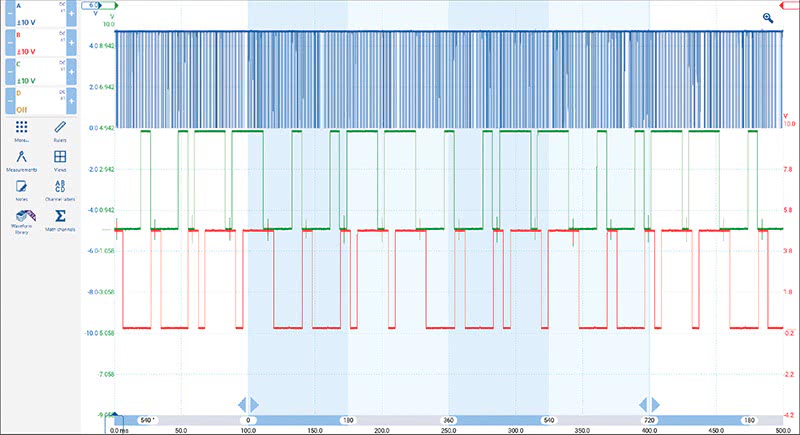
The usual suspects, spark plugs, fuel injectors, coil, MAF and a few other goodies were all thrown at this Volvo, but to no avail. As we interviewed and worked with this technician through his previous diagnosis to where we were now, we decided to cut to the chase and do some mechanical waveform analysis, as it didn’t seem they were getting to the answer with the scan tool and the machine shop. We decided to hook up the scope and overlay the cam sensor, crank sensor, and in-cylinder pressure waveforms to see if we could determine quickly what was going on with this car.
What was the issue? Electrical or mechanical? We needed to narrow this down first.
Once we scoped the car and gathered and saved some different files of the engine and sensor characteristics, we realized that there were really no indications in the ECM signaling versus the mechanical cam and crank timings that would cause this misfire issue in cylinders 1 and 2. After some further quick data checks to the air and fuel sides of the engine, our support crew decided that whatever this was, the computer was not happy with what it was seeing going on with cylinders 1 and 2. So what now, when everything checks out okay?
The Engine IS the Modulator for the Electronic Control System
Remember earlier we mentioned the engine is the modulator for the electronic control system? This case and the next 2015 Volvo right behind it (in the same week, believe it or not), proved this beyond a shadow of a doubt.
Think about this; a set of crankshaft sensors and camshaft sensors are reading the rotating shafts via toothed wheels or reluctors, calibrated to the camshaft and crankshaft’s true position, and the ECM’s misfire algorithm essentially analyzes crankshaft speed variations to determine misfire (see Figure 1A). What happens when twice or three times (at the cost of many arduous hours), we test over and over to find that, beyond a shadow of a doubt, these mechanical timing marks and sensors are indeed lined up properly, synchronized, and functioning perfectly, yet we still have the issue?
Could it be ECM programming? Possibly, but in this case, there were no posted TSB bulletins nor ECM software updates found specifically for our problem. Plus, the vehicle also has a new and freshly programmed ECM anyway, so there’s that.
And there’s the fact that the cylinder head has been off three times and back to the machine shop for so-called valve adjustments; there’s that too.
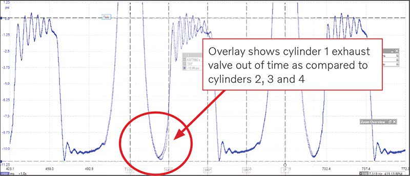
Figure 3 shows the next test, which was an individual cylinder overlay of cylinders 1, 2, 3 and 4 for comparison.
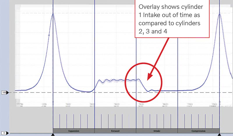
We decided to ask the technician to record and save in-cylinder pressure waveforms under very strict setup conditions for each of the Volvo’s four cylinders, so that a comparison could be made across the entire engine. This test is what we often use to determine several engine characteristics that can definitively diagnose things like broken or worn valve springs, valve leakage, and tough-to-find conditions too, like a worn camshaft lobe on one cylinder. But in this case, we were using the overlay test to check the gas exchange section (where the valves are opening and closing to exchange air) and making sure all four cylinders had exactly perfect overlays as compared to the others. Here, we saw our problem relatively quickly, but solving it would be the challenge. Figure 4 shows the variance of the exhaust valve opening on cylinder 1.
Once we performed the in-cylinder pressure waveform overlay and identified the issue, we advised the shop owner to remove the cylinder head once again, to see what the trouble was. This time, we had the shop disassemble it themselves, and purchase the Volvo special tools setup jig for the cylinder head valve adjustment. See Figures 6 and 6A for tool callout.
An Overhead Cam Machine Shop Trick is Uncovered
Upon disassembly of the head for the umpteenth time, it was discovered that the machine shop, in rebuilding the head, had used a technique called “Tipping the Valves,†which allows the machine shop to quickly set valve lash when setting up the head. Tipping the valves involves grinding down the tip of the valve stem itself so as to adjust the valves to the lifter buckets in the head. This of course, is a risky way to adjust valves in most production engines, but yet, we find this is becoming a more common practice, as we untangle some of these gnarly diagnostics.
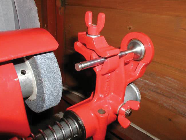
If we grind the valve stem instead of using the camshaft tools for measuring and setting up the lifter buckets properly to adjust lash, we necessarily change the valve installed height. Doing the valve adjustment this way led directly to the problem on our S60 T5; the machine shop, thinking only in terms of valve lash adjustment, and lacking the Volvo camshaft jig for valve clearance adjustment, actually ended up changing the camshaft’s timing on the opening and closing of the valve in that one cylinder, as shown in Figures 3 and 4.
This is exactly what the ECM was seeing in the form of a slight difference in crankshaft speed due to the difference in valve opening times, which triggered a misfire DTC in cylinder 1 and the cylinder next to it while the engine was running.
To the humans—the driver, the technician and the shop owner—this misfire was entirely imperceptible while operating the vehicle. However, once the dreaded misfire code set and the drive cycle criteria were met, of course the ECM knocked out the injectors on cylinders 1 and 2 on which it saw the problem occurring. So, no matter whether or not you could feel a misfire before the codes set, you certainly couldn’t drive it once injection was disabled in cylinders 1 and 2.
The fix for this vehicle was to replace the valves and set the valve lash properly using Volvo special tools.
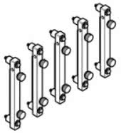
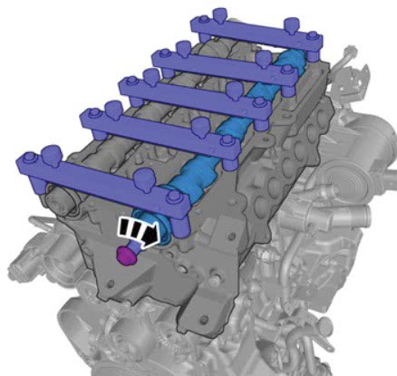
The instructions show that once the cam jigs are set up, the cams are rotated clockwise, and valve lash is to be obtained by using the tappet (out of the set) that provides the proper lash. This procedure was clearly not done this way and as a result, the valves were ruined and had to be replaced.
The second case, a 2015 Volvo S60 T5 (same engine) was even more confusing. We had essentially the exact same codes, cylinders 1 and 2 misfire, and this car was also experiencing no perceptible misfires. Strangely, the cylinder head had also been off this car twice and at the machine shop for the same reasons.
When this vehicle showed up on the support line two days after the first, we thought we would find the exact same problem. After a basic discussion with the technician about the external misfire-causing possibilities, plugs, coils, injection, etc., we decided to run the same tests as we did on the first vehicle above. Strange thing here was, we did not see any of the valve opening variance we saw in the other engine. So what gives?
What we did notice was that the intake cam was advanced by about 13 degrees (subject to cursor placement on the waveform), so we advised the technician to correct this. Indeed, once this was corrected, we all felt confident that the issue was solved. But not so much. Upon startup, this car had the exact same condition as before, the misfires set and the cylinders went dead.
After a fair amount of scan data analysis and a retest of the engine mechanical waveforms, we determined that we still could not detect any mechanical cylinder variance whatsoever upon rescoping the engine and performing the overlay. This vehicle, unlike our first S60, had something external causing the fault. The problem here was that, between the engine repair and first and second valve adjustment attempts by the machine shop, everyone involved, us included, suspected something mechanical for obvious reasons. This focus temporarily derailed all of us by focusing on that engine repair.
As the diagnosis continued, a quick look at the MAF sensor with the scope gave us a slight clue that led us to the eventual fix. Most normal analog MAF sensors, when idling, will read approximately 1.2 to 1.4 volts on the signal wire. When the throttle is snapped to WOT, the MAF signal should make about 4.0 volts at wide open throttle and then fall back to idle voltage as seen in Figure 8. On this car, we were only seeing about
0.8 volts at idle on the MAF. Hmmm…
We snapped the throttle twice as prescribed and measured about 3.6 volts at WOT. Looking at the fuel adaptations, we noticed that the long-term fuel trim was adding about 8% at idle, which corrected itself to about 3% off idle. At this point, we disconnected the support session and decided to reconnect in the morning. We decided before disconnecting to look at the cranking intake vacuum waveform to confirm whether this was an air-side problem. The support session ended until the next morning.
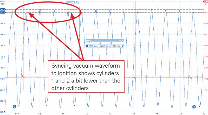
That evening, the shop owner and technician went over all of the work and steps done putting the engine back together, just to see if anything was awry. The next morning, we received a call from the shop saying that they had located a line and grommet near the front of the engine that was not seated correctly and was leaking vacuum slightly. Upon correcting this mechanical issue, the vehicle was cleared of codes and road tested and returned no misfire codes.
In going through these two Volvos this week, we all learned a few lessons. First, the practice of “tipping the valves†for adjustment of lash can return some ugly results, in the form of tight valves that measure fine while cold on the bench, but not so much in the heat-expanded, warmed up engine. This practice had created problems on both of these cars.
Secondly, if ground down too far, tipping the valves can change the camshaft’s timing of the valve opening and closing significantly. It can be argued that for race engines and other applications, tipping the valves often produces a good result when done with skill and precision. But for adjusting lash on a passenger car cylinder head, rather than taking the time to use the factory tools and valve lash procedure, we’re often asking for trouble, as was the case with the two vexing Volvos we tangled with this week. Third, mistakes can be made on reassembly!
The lesson we learned is to never let the back story drive our diagnostic direction. In this second case, because the engine had just been apart twice, the technician was insisting that the basics had been well covered (along with the seemingly exact condition on the previous Volvo we had just solved). Our internal lesson is that we probably should have insisted that we spend more time asking the technician going back to the basic checks first rather than jumping straight into the mechanical measurements.
It just goes to show you that any and all of us can easily out-tech ourselves when approaching these modern-day driveability issues. Sometimes the issue is mechanical and not electrical. We need to always have in the back of our minds that the engine is the modulator and can cause all manner of DTCs that would seem on the surface to be electrical in nature. This was the case in both of our Volvo cars this week. But because of persistence and some good old targeted physical testing, we have two victorious Volvo owners happily driving their cars home again, and two techs and shop owners breathing a sigh of relief.


Shame on manufacturers for building engines or anything else that require specialized tools of this nature. I believe it is a way to tie the vehicles to the dealer and not allow independent shops to work on their products without purchasing expensive single use tooling.
Excellent, nicely prepared arcticle. The motoring public has no clue as to what we are doing in this line of work. I for one have experienced tremendous changes in the 55 years of service and repair in my Volvo independent business.
With respect,
Larry Sheldrick