
To help minimize potential weakening of adjacent panels, reinforcements, corrosion protection, and other critical body elements, Volkswagen recommends partial replacement of the Golf luggage compartment (trunk) floor pan if it has received collision damage. Here you’ll find detailed examples of steps in the sectioning and replacement procedures for a 2015 Golf.
Volkswagen allows partial replacement of the trunk floor on the 2015 and newer Golf. There are specific OEM-required procedures to help restore the Golf trunk floor to pre-collision condition. It’s not complicated. You’ll cut the replacement floor pan at a VW-recommended separating line, substitute MIG/MAG plug welds where factory spot welds are in inaccessible locations, and replace some factory-applied adhesive with MIG/MAG plug weld seam welding.
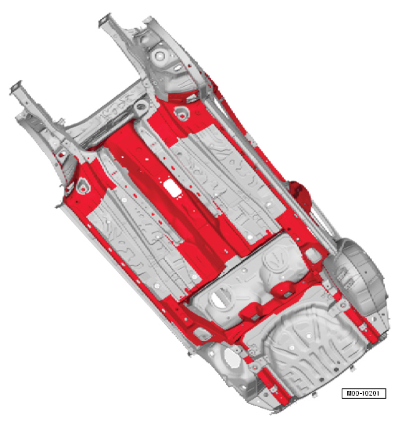
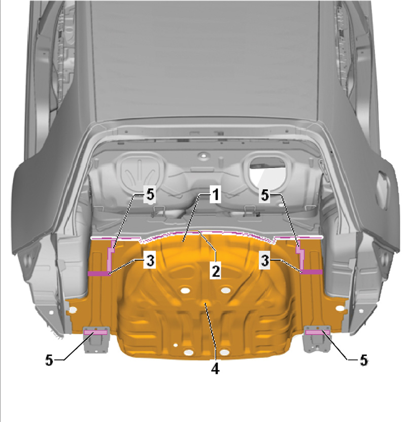
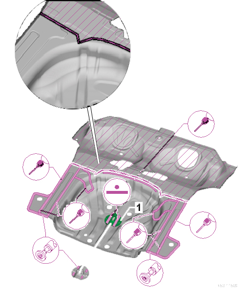
The trunk floor pan is joined to the rear frame rails, the rear crossmember, and the rear cross panel. Proper location of a sectioning cut and repair is critical to maintaining structural integrity in the event of a future rear end collision.
Other engineering design factors make cut location critical. For example, corrugation patterns in the 2015 Golf trunk floor are computer optimized to improve sheet metal rigidity, which in turn reduces the amount of sound insulation needed. Smart. Consequently, the cut location is in the one area of the floor pan that is relatively flat and corrugation-free from side to side. See erWin® for exact cut location details. Don’t second guess them.
Sectioning the trunk floor pan
You should already have removed the rear cross panel (rear body panel), as any damage that is significant enough to require floor pan replacement has likely also destroyed the cross panel. Make a separating cut in the existing trunk floor pan, along the front edge of the spare tire well. Do not cut deeper than the panel thickness, to avoid damaging the crossmember reinforcement under the floor pan.
Note that the replacement trunk floor component does not include a new retaining bracket for the spare tire. Separate the old retaining bracket so you can re-use it on the replacement trunk floor. Remove any adhesive and sand down to bare metal the areas to be welded. Refer to erWin® or ElsaPro for weld-through primer instructions.
Replace some factory spot welds with MIG/MAG plug welds
The trunk floor pan is joined to the rear substructure during factory production using spot welds and structural adhesive. Drill out spot welds from the spare tire well portion of the floor pan where it meets the crossmember, frame rails, and the supports that extend down along the vertical wall of the tire well on each side. Separate the adhesive bonded edges and discard the old floor pan.
Remove any residual adhesive from the exposed rail, crossmember, and spare tire well support surfaces. The adhesive applied at the factory will be replaced with a MIG/MAG (gas-shielded continuous arc) plug weld seam. One exception is the bumper support bracket at the end of the frame rail. There, new two-part body adhesive (part number D 180 003 M2) will replace the factory adhesive on both sides of the bracket. The adhesive mixing tip assembly includes a connecting piece (part number D 002 003) and static mix (part number D 002 001), and is included in the two-part adhesive kit part number D 180 003 M2).
Clean away any corrosion and dirt, and sand down to bare metal the areas to be welded. Do not apply weld-through primer when weld bonding.
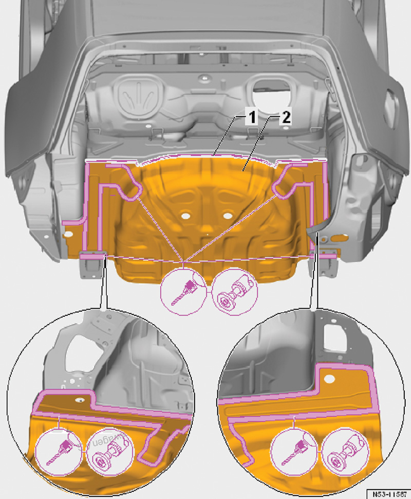
Transfer the separating cut to the new trunk floor pan. You will place the part of the replacement floor pan that is nearest the back seat area so that it overlaps the cut end of what remains of the old trunk floor.
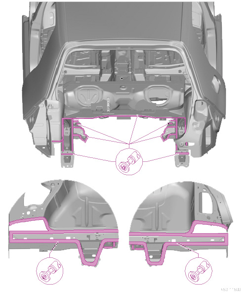
The cut edge is too far in for even the longest spot welder clamping arms, hence the MIG/MAG plug welds. Where the floor meets the rear cross panel, easy access allows resistance spot welds.
Foam matters
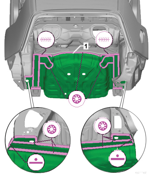
Structural foam inserts (SFIs) reduce the transfer of road noise, vibration and harshness (NVH) into the passenger compartment. It is almost magical how computer modeling has helped Volkswagen engineers select the ideal location, size, and amount of structural foam inserts to maximize NVH reduction while minimizing added weight and bulk. There is one molded structural foam insert on each side of the spare tire well, in cavities between the rear longitudinal member (frame rail) and the floor pan.
Inspect the existing molded foam insert to make sure that it has not lost its shape or flattened out. If it is in good condition, save and reuse it when you install the replacement floor pan. If not, cut out a replacement insert from a universal molded foam closeout panel (part number 000 864 663).
Remove any old foam material and adhesive still stuck to metal surfaces prior to installing the new or reusable foam insert. Make sure that each cavity is clean and then apply corrosion protection. Attach the bottom of the foam insert to the cavity using butyl sealing cord (part number AKL 450 005 05) or two-part filler foam (part number D 506 KD1 A3). Then apply butyl sealing cord or two-part filler foam to the top of the insert.
Do not substitute alternative bonding agents. For example, hot melt adhesive can bond, but does not have good sealing properties. Butyl tape (AKL 450 005 05) or the Volkswagen-approved two-part filler foam (D 506 KD1 A3) offer both adhesive and sealing capabilities. Similarly, some adhesives solidify when completely cured, which weakens the NVH reduction benefit in this application. Volkswagen-approved butyl tape (AKL 450 005 05) or two-part filler foams (D 506 KD1 A3) never harden.
Two-part filler foam (D 506 KD1 A3) cures within 25 minutes, so do not apply it until you are ready to install the new floor pan. Do not perform any gas-shielded welding within 15 mm of areas containing structural foam inserts.
The right adhesive

Structural components, body panels, roof, glass, and other automotive parts may each call for a different formulation in areas where adhesive bonding is required. Volkswagen engineers have tested and validated which adhesive formulations best provide the joint strength and long-term durability on a given metal type and thickness.
Apply two-part Volkswagen body adhesive (D 180 003 M2) to the forward-facing side of the bumper bracket, above the frame rail. Position the replacement floor pan and check fit using frame bench attachments.
Install the new floor pan within 90 minutes. Position the new panel making sure not to lift it up, as lifting will create air bubbles and weaken the bond. Make adjustments to the panel fit by sliding, not lifting.
Overlap
Lay the replacement floor pan so that its front overlaps the portion of the old floor pan that remains after you have completed your separating cut. The overlap must be wide enough to allow room at the cut end for new MIG/MAG plug welds with a diameter of 7 mm.
Use MIG/MAG plug welds everywhere except at the connection between the floor pan and the rear cross panel (rear body panel), where you will use resistance spot welding.
For each welding area and type, it is wise to practice on scrap pieces of the same gauge, and using the same welding angle (horizontal, vertical, or overhead) as the repair will require. Do destructive testing on your scrap welds. When you see good weld penetration, you’ll know you’ve got the heat and wire speed settings just right.
Follow the VW-approved repair procedures, and restoring the Golf trunk floor to OEM standards is not complicated at all.
Download PDF


0 Comments