

There is a surprisingly long list of ways in which failing to perform pre- and post-repair scans can ruin a collision technician’s day. Read on for examples of how scanning for trouble codes can assist with diagnosis of both collision-related and repair-induced problems.
Collision damage to electronic and electronically-controlled components may not be easily identified through visual assessment. Additionally, many electronically–controlled devices need calibration or re-initialization after any remove-and-replace procedures, making post-repair scans essential to completing the job.
Nissan is leading the industry in encouraging collision repair specialists to use pre- and post-repair scanning to both plan and verify the effectiveness of repairs. The company recently released Position Statements that identify several categories of repair for which post-repair calibration or initialization is critical, and that explicitly make post-repair scanning mandatory for all collision repairs.
The benefits are many. Nissan’s Position Statements will lead to more complete and accurate estimates and more efficient repair processes, as well as help collision repair facilities get more of their work approved by insurance claims adjusters, often without the need for job-delaying supplement approvals.
New technologies that enhance safety and convenience are embedded in exterior and interior locations throughout the vehicle. These can include, depending on the vehicle model, cameras that see behind and to the sides of the vehicle to assist with backup and lane keeping, plus radar/sonar that looks forward for cruise control and collision avoidance functions.
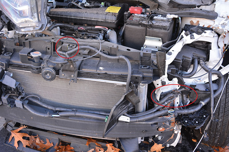
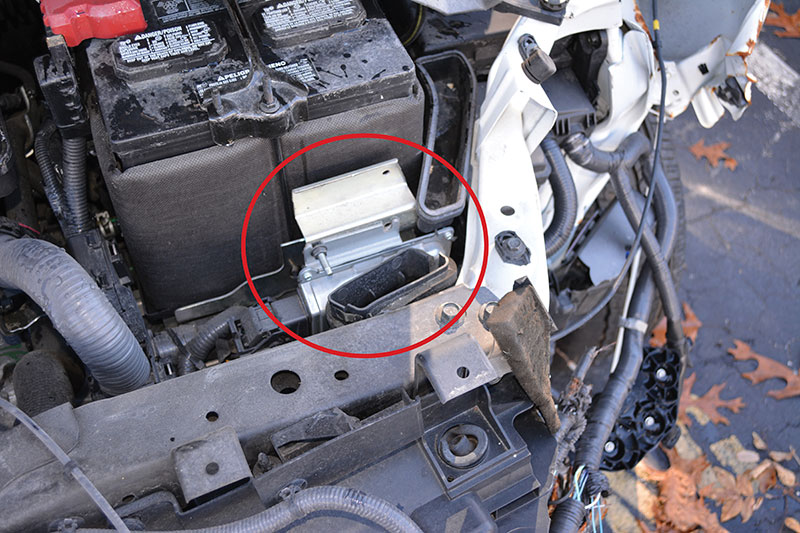
There will likely be sensors that input data for vehicle dynamic control (VDC), traction control (TCS), anti-lock brakes (ABS), and supplemental restraint systems (SRS), including airbag, seat belt pre-tensioner and occupant classification systems (OCS) for front passenger weight determination, and other devices. These safety technologies may be embedded in bumper covers, exterior body panels, in the windshield, or mounted near or at the rear view mirror, wheels, underhood and in other locations.
New Nissan vehicles incorporate many electronically-controlled comfort, information, and entertainment technologies. These too are vulnerable to collision damage. Rain-sensing wipers, one-touch windows, and temperature-controlled seats are just a few examples.
No warning lights
Many of these safety and comfort technologies do not set a dash warning light when there is a fault. Or, as a subset of a larger system, they may set a light that requires further diagnosis to determine its specific cause. For example, a fault in the Steering Angle Sensor (SAS) circuit, which sends steering wheel rotation amount, angular velocity, and rotation direction information to the ABS actuator and controller, may cause the ABS lamp to illuminate. Nothing on the dash will specify, however, that the SAS is the source of the problem.
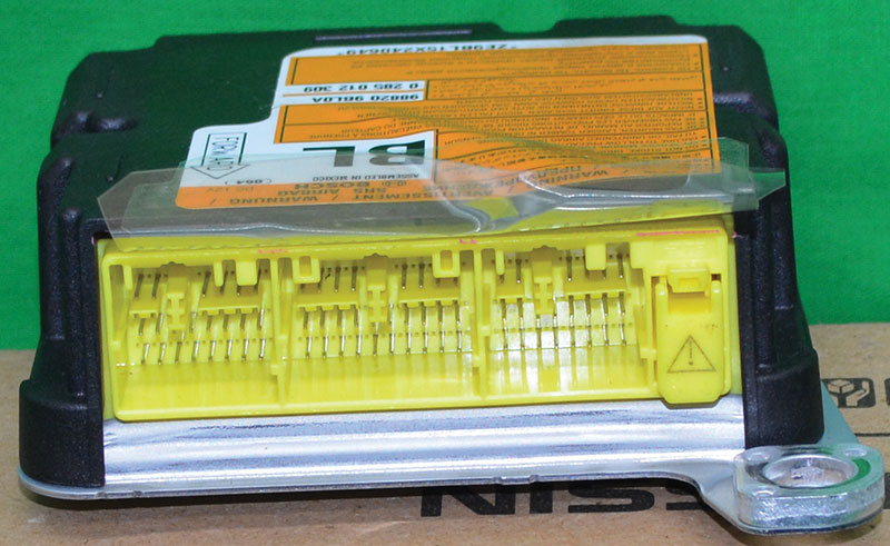
For that, you’ll need to scan for trouble codes. And you’ll get the most current, accurate results using CONSULT III Plus, the Nissan factory scan tool. It contains the build data listing all of the components and systems on Nissan vehicle models.
Critical condition
The SAS is critical to achieving an accurate wheel alignment. It is also a major contributor to the VDC and TCS.
The stability control system continuously collects SAS data that tells it where the driver wants the vehicle to go, and compares it to the current actual vehicle direction as recorded by sensors measuring lateral acceleration, yaw rate, wheel speed and other key indicators. If the data does not match, the VDC applies braking power to individual wheels to create torque in the opposite direction, pulling the vehicle back to the driver’s intended path.
Easily misdiagnosed
When a vehicle is driving straight ahead with the steering wheel straight, but the SAS is not set to zero degrees, things can get tricky. The electric power steering (EPS) thinks that the driver is trying to do something other than go in the direction in which the vehicle is pointing. The driver may compensate without conscious effort, if the vehicle is going down a straight road, and the SAS is off only a little. In a tight curve, such as onto a highway on ramp, the VDC may start corner braking because the conflict between the vehicle direction and the SAS data implies that the driver is nearing an out-of-control situation.
Without scanning for trouble codes, SAS faults are therefore easily misdiagnosed. An incorrectly calibrated SAS causes the EPS to constantly try to return the steering wheel to what it believes is the centered, or zero, position. The vehicle owner may bring the car into your shop with a tire or steering wheel vibration complaint, or with uneven tire wear patterns. They may have their tires balanced, or even purchase new tires, but that won’t solve the problem.
DTC C1144: SAS Neutral Position Adjustment
Even if the SAS has not been impacted, you must check that the SAS is reset to the neutral (zero degrees) position after a collision. Nissan has a dedicated Position Statement on when calibration of SAS is necessary. It, as well as other Position Statements, can be found at collision.NissanUSA.com. After many procedures that are often part of collision repair, SAS neutral position adjustment is mandatory. Such procedures can include removal or installation of the SAS or other steering or suspension components, replacement of the ABS actuator or controller, and wheel alignment.
Trouble code C1143 is set when a malfunction occurs in the SAS circuit. Code C1144 sets when the neutral position of the SAS is not at zero with the front wheels pointed straight ahead. SAS problems that set either of those codes will also cause traction control and stability control functions to be disabled until the DTC is erased.
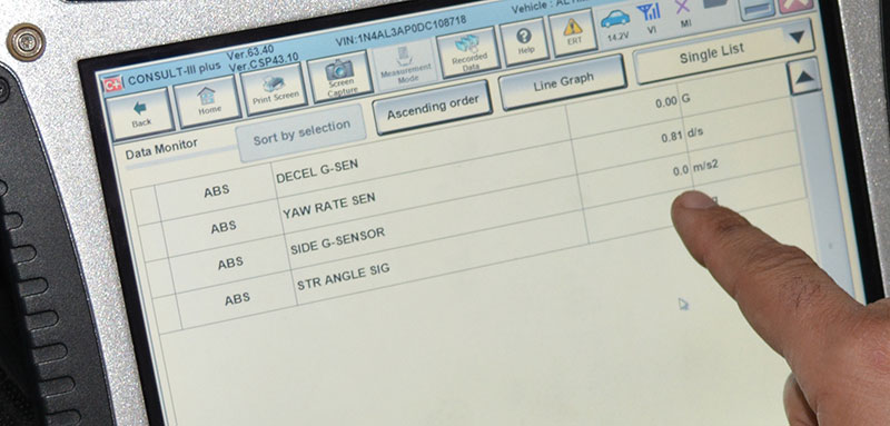
Codes will also set, and disabling of VDC and TCS functions will occur, when a yaw rate, side or decel G sensor circuit is open, shorted, or has a malfunction (C1145 and/or C1146). When calibration of yaw rate, side or decel G sensor has not been completed (C1160), add ABS and electronic braking distribution (EBD) to the list of disabled driving assist functions. See service manual section “BRC†(Brake Control System) for additional information.
Of course, all sensor calibrations are dependent upon having accurate vehicle centerline (thrust angle) information available through the appropriate controller.
Scanning is believing
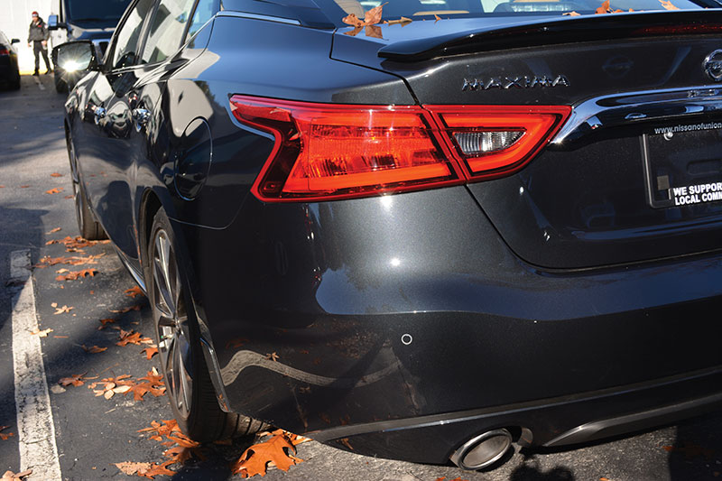
Some damage can be missed simply because the sensor is embedded in a bumper fascia or other part, and problems can be difficult to detect through visual inspection. Scanning for trouble codes prior to beginning repairs will alert you to whether a bumper includes sensors or imaging technology that have sustained damage. If so, replacement of the bumper fascia is the preferred option. The application of plastic filler over bumper or fascia damage is likely to obscure a sensor, rendering post-repair calibration of that sensor impossible.
Nissan has issued a Position Statement requiring that any replacement must be performed using only Genuine Nissan bumper fascia panels. Depending on the model, there is sonar or other imaging technology in Nissan bumper fascia.
Aftermarket or recycled fascia may have differences in build specifications that result in issues with sensor alignment and performance. Some non-OE fascia panels may come without pre-drilled holes for sensors. This forces the body shop to cut the openings, introducing potential measurement or placement error, along with requiring time-consuming extra labor. For additional information about bumper fascia replacement, refer to the Nissan service manual section “SN†(Sonar).
Pre-scanning can also lead you to information about related items that are affected by the repair even if they were not significantly damaged in the collision. Any windshield replacement on these vehicles also requires replacement of the rear view mirror. It may not show up as a trouble code due to impact damage, but rather as an “included item†related to the windshield being replaced.
Complete the repair: calibration
Many Nissan vehicles are equipped with sonar sensors as part of their “Safety Shield Technology.†They contribute to the proper functioning of Nissan’s Forward Emergency Braking (FEB), Predictive Forward Collision Warning (PFCW), and Intelligent Cruise Control (ICC). In addition to collision impact, any removal, reinstallation or shifting of these sensors require they be recalibrated after the repair. Failure to follow this recommendation could result in sonar malfunction or in safety features not working as intended, thus posing a significant risk to vehicle occupants. Refer to service manual section “CCS†(Cruise Control Systems) for additional information.
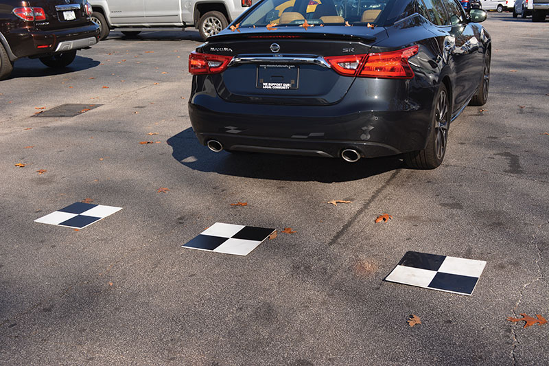
The 2017 Nissan Maxima®, Murano® and Pathfinder® models are now being equipped with Around View® Monitor systems, which use cameras placed in the front, rear, and both sides of the vehicle to give the driver a 360 degree view of nearby traffic and objects. Although a frontal collision has always had the potential to knock a sensor in the rear fascia out of calibration, now no matter where these cars are hit, there may be a camera near enough to have sustained damage. Pre-scanning for trouble codes will help identify any camera or other imaging device that has sustained damage and must be included in the repair estimate.
A Nissan Position Statement released this past summer makes it mandatory that after removal or replacement of any camera, or camera mounting component, including the front grille, door mirror, or others, the affected camera must be calibrated before the vehicle is returned to use. Failure to follow the required calibration procedures could result in Around View Monitor systems not functioning as originally intended. Refer to the service manual section “AV†(Audio-Visual & Navigation System) for additional information.
Similarly, any time the front passenger seat, or any component of that seat system, is removed and replaced, a Zero Point Calibration of that system is mandatory. The front passenger seat includes the Occupant Classification System (OCS), which includes a scale to weigh the occupant and determine if they weigh enough to safely deploy a front passenger airbag in the event of a collision. The scale is built into the seat and cannot be repaired if damaged. It is extremely sensitive, and the scale in a replacement seat must be calibrated to ensure proper operation.
Control unit configuration
If you replace the audio-visual control unit or the ABS controller, you must save (in CONSULT) the system configuration of the existing control unit prior to its removal. Only then will you be able to write the system configuration details into the replacement control unit, which is shipped blank. Without the proper control unit configuration, you will be unable to calibrate a replacement camera, Around View Monitor, or decel G sensor. Because the ABS ECU handles SAS calibration, without the proper system configuration it will be difficult to complete the steering angle sensor adjustment to its neutral position.
Nissan has also issued Position Statements declaring that due to structural integrity, safety, and fit and function concerns, the company does not approve the use of aftermarket, gray market, or imitation parts, and in particular, does not support the use of aftermarket or recycled glass.
One example might be the front windshield, where in addition to structural integrity concerns, the integration of imaging technology brings potential calibration issues when aftermarket glass is considered. If an aftermarket windshield has a slightly different curvature than the factory replacement, or as a result of poor manufacturing quality has “waves†in the glass surface, you may have difficulty calibrating any sensor or imaging device mounted on that windshield or embedded in a windshield-mounted rear view mirror. Nissan will not be responsible for any subsequent repair costs associated with a vehicle or part failure caused by the use of other than Genuine Nissan replacement parts.
See the Nissan service manual section “AV†for additional information about AV control unit configuration. See section “BRC†(Brake Control System) for ABS control unit configuration. Refer to service manual sections “GW†(Glass & Window Systems) and “MIR†(Mirrors) for additional information about the windshield and rear view mirror.
Post-repair scanning
Scanning for trouble codes after repairs have been made will confirm that problems identified in the pre-scan have been properly repaired and that all vehicle systems are communicating as specified. Additionally, post-repair scans can detect new trouble codes that may have been set as a byproduct of the repair procedures themselves.
Thanks to the spread of electronically-controlled devices through almost every system on modern vehicles, trouble codes that had not been present before the repair can be introduced due to the fact that disconnecting from their power source makes many devices require re-initialization and calibration. Tiny connector pins are fragile and easily damaged when bumped or shaken during nearby repair activity, or even just from the process of removing and re-installing them.
For both reasons, new codes are often set during the repair process. Nissan has issued a Position Statement making post-repair scans mandatory on all their vehicles following a collision repair.
1-touch
Nissan vehicles are now equipped with power window features that include “Auto-Up,†“Anti-Pinch,†and “Retained Power†(to function normally for 45 seconds after the ignition switch is turned off). These features may not work even after a minor collision impact.
Many repairs can separate the power windows from their power source. These can include a blown fuse, disconnection of the negative battery cable or harness connectors for the power window and door lock/unlock switches, removal of the motor from the regulator assembly, or removal of the door glass or its door glass run. In such cases the Auto-Up and Anti-Pinch features must be re-initialized. Failure to initialize these features after repairs could result in the power windows not functioning as designed.
There are brief but specific sequences of post-repair steps for initializing the window up and down operation, and for confirming that the Anti-Pinch and Retained Power features are fully functioning. See the service manual section “PWC†(Power Window Control) for additional details.
Walk like a mechanic
Collision repair must now include pre- and post-repair scanning for trouble codes, calibrations, re-flashing, initializations and output tests to verify that all systems on the vehicle are performing and communicating per factory specification. Welcome to the world of mechanical repair.


0 Comments