
Moving that boiled-down dinosaur from a builder’s perspective…
Once I check it by measurement, I double-check it just before I install the pan with clay. The best way I’ve found to do this without making a mess of things is to work the clay in my hands until it’s nice and warm and soft and then wrap it in a double or triple layer of cling wrap so it can’t extrude into the screen or stick to anything. I lay it on top of the pickup, bolt the pan down with a few fasteners, pull the pan and section the clay with a razor blade and check my distances.
If you race at any level, you spend a lot of time and money pursuing your hobby, something I’m sure we’re all painfully aware of by now. Worse, if you race at or near the top of your class you spend more and more money for less and less return because the last few trick parts or processes it takes to get you there are the most expensive on a dollar-per-position, dollar-per-horsepower, or dollar-per-point basis.
While the glamor parts like cylinder heads, camshafts, valve control systems, intake, headers, and fuel delivery get all the glory, none of it is worth any more than current scrap price without a well-designed and reliably-functioning oiling system because without it all those parts just become something to drive over when the engine scatters.
Oil itself is big science these days. It provides lubrication and cooling, it contains detergents to clean and surfactants to hold contaminants in suspension until they can be filtered out, and it provides corrosion protection for every internal engine piece. The right oil with the right viscosity at the right temperature delivered with the correct pressure and in sufficient volume combats metal-to-metal contact, scuff and gall, flows easily when cold or warm and absorbs and dissipates as much as 15% of the waste heat generated by your engine.
Fast drain & fill
The pumping elements of a positive displacement oil pump come in a number of configurations. I dug around the shop and came up with these examples for you, but I’m sure that as technology has continued its onward march there are others out there.
The spur gear pump has a couple of advantages in that it can make a lot of pressure and volume and it can handle a good bit of wear material and swarf. Not every design likes wear material moving through it and a gerotor pump will lock up and twist off the drive rod if it’s forced to chew up a lot of wear shrapnel. Increasing the overall length of the gears and deepening the housing makes the move from standard-volume to high-volume. Gear pumps tend to generate a busy pulsing flow that steadies up with increased drive speed, something you can easily detect if you prime an engine equipped with one. You can feel the rolling gears in your hand through the drill.
Which oil you use, what weight and what type are topics for another time, but whatever oil you use you have to concentrate it in sufficient volume to feed the oil pump suction side without inducing air or cavitation, pull it into a pump, pump it through the oil distribution galleries or hoses, get it back into the oil pan, and gather it up again for another circuit through the engine, all at volumes varying between roughly two gallons per minute at idle and over twelve gallons per minute at redline. Think about that for a second. The pan is being emptied and refilled at a rate of over five times per minute — as often as once every seven or eight seconds in the worst case scenario for a six-quart system! In the meantime, we’re dealing with blow-by at high engine speeds as the rings become less stable, a violent, shifting pumping of the crankcase caused by the pistons bobbing up and down on alternate banks, oil that is caught up on the crankshaft and entrained with air, and the whole mass looks like a giant taffy pulling machine like you used to see at the state fair. (Go to https://www.youtube.com/watch?v=B0Ls3MFeJv0 in case you forgot what that looks like!) The video below shows a quick simulation of engine oil splash and crankshaft interaction:
In addition to all that havoc, you’re dealing with the results of an oil pump drive attached to the other end of your distributor (maker of sparks and keeper of timing), which is subject to surging, pulsing loads caused by changing rpm, and the oil pressure relief valve opening and closing tossing your spark control out of whack. What you end up with is another excitation force applied to the camshaft, valve train and timing drive system, often imparted at the camshaft end opposite the primary source of cam excitation originating at the crankshaft driving the cam as each cylinder-firing event accelerates the crank and, through the drive system, the cam. Designs that have the distributor at the front of the engine suffer less, but any time you apply multiple forces from different sources to a single component the chances of hitting destructive sympathetic or resonant frequencies increases. Are we having fun yet? We ARE having fun, right?
. It’s quite robust and can handle contamination fairly well without locking up. Increasing the volume capacity is as simple as increasing the depth of the pump pocket along with the drive and driven members. Of course, you could also increase the diameter if the available space allows. It’s well-balanced with large suction and discharge cavities that end up opposed to one another, but with the added support of the fixed crescent and the large diameter center of the drive gear, which is mounted to either the torque converter (in this case) or the crank nose.")
The crescent and internal gear pump has been the primary fluid mover in automatic transmissions for many years. This example is from a Ford C-6 transmission, but it’s nearly identical to any pump of this configuration used as the oil pump in later model engines where the pump is driven from the crank nose at engine speed. The main strengths of this type of pump is that the pulsing rate and volume are high enough that it provides a very clean hydraulic signal wherever it’s used and it can easily develop the extremely high pressures typically required for transmission operation (but not necessary in an engine). It’s quite robust and can handle contamination fairly well without locking up. Increasing the volume capacity is as simple as increasing the depth of the pump pocket along with the drive and driven members. Of course, you could also increase the diameter if the available space allows. It’s well-balanced with large suction and discharge cavities that end up opposed to one another, but with the added support of the fixed crescent and the large diameter center of the drive gear, which is mounted to either the torque converter (in this case) or the crank nose.

The twisted lobe gear shown is from a Peterson dry sump R4 pump and it’s a fairly new design. It’s a variation of a lobed pump, like that found in a straight rotor Roots blower or in some industrial high pressure fluid movers. The main advantage to a lobed pump is that it has a very high capacity to handle garbage. In fact, lobe pumps are often used as trash pumps or to move things like foods, such as cherries or grapes with minimal damage, obviously sized and operated at speeds compatible with such delicacies. For an oil pump application, the large volume of the rotor allows most damaging material to move around the through the cavity without causing catastrophic damage, although it’s not uncommon for the lobe face to become scarred enough over time to require replacement. As long as the tolerance between the lobe face and the housing it lives in is good, it’ll make good pressure and volume.
The nice part of the dry sump system is that it’s all rebuildable and it’s external to the engine, so if something develops mid-season a couple of bolts, a half dozen hoses and removing the drive belt is enough to land it on your workbench for repairs. The other good part is that there’s a selection of drive and driven pulleys available in different tooth counts and should it be needed you can speed the pump up temporarily to get you through until you can get back to home base and get it fixed. Of course, if your problem is sudden and extreme, smart money says shut it off and conduct full engine forensics, because increasing pump speed in that case is like putting a Band-aid on a bullet hole and what happens next will not be good.
Two varieties

The gerotor pump shown is a Titan billet pump that we ran a few seasons and it’s a good example of the breed. Gerotor pumps are efficient and smooth mechanically, but they suffer from some hydraulic noise because the pumping elements are located off center and they generate uneven pressure loads that can make them vibrate and shake the drive system. Increasing volume is as simple as increasing the drive and driven element length, but they don’t like to digest things that aren’t oil.
If you roll a gerotor pump through, you’ll see that the end of the rotor passes very close to the ring and any little bit of crud that gets into the pump can ( not necessarily will, but can) lock it up. Over the years, of all the pumps t I’ve found locked, this type probably accounts for 90% . Now, you could ask, “If it’s got that much junk passing through it, don’t you have bigger problems?†Of course, the answer is yes. I’d just prefer that my oil pump not be the “fuse†to detect and protect the developing engine problem! I’d prefer to catch it by inspecting the oil filter or with a driver who’s situationally aware, but I understand that in the heat of the race that’s not really what he’s thinking about or focused on.
Oil systems come in two variants, wet sump and dry sump. A wet sump system is most common and the one used for generations of street-driven vehicles of all types since the earliest days of the automobile. A small-capacity storage area is created in the oil pan, which is shaped to provide a reservoir for oil, and an engine-driven pump is either submerged in the oil or connected to the oil in the pan through a pickup pipe located within three-eighths to a half inch of the floor of the deepest part of the pan. Wet sump systems and wet sump oil pumps work quite well in low-power or steady-state or stationary applications, but their inherent weaknesses begin to manifest themselves as power output increases, the operating range widens, the engine is operated continuously between closed throttle and wide open throttle (you know, like racing…), or if the vehicle is exposed to extreme G-forces during cornering or acceleration.
A dry sump system is exactly what it sounds like. The pan is as flat as it can be and still provide clearance for the parts moving inside it and the necessary kick-out needed to catch oil, with no internal engine storage capacity. The pan remains largely dry other than for whatever liquid lube is moving through it as it collects the oil leaving the lubricated parts, which is then quickly pulled from the pan by one or more scavenging pump sections plumbed into the side of the pan. Oil storage in a dry sump-equipped vehicle is accomplished by using a remotely located tank plumbed to and from the engine by properly designed and sized hoses.
There are surprisingly few factory-installed dry sump oiling systems out there, due in part to what has to be a corporate cost versus benefit analysis, and in part because they are more complicated and not really needed at the performance levels most commercial road cars can attain. The few that exist are confined to some of the exotic Europeans like Porsche and Ferrari, although a hybrid dry sump shows up on a few LS engines and Corvettes. If this latest performance and horsepower race continues another few years, I’m sure we’ll see more of them appearing on our road cars.
Too tall
For racing, one of the big disadvantages of a wet sump is that it requires a fair bit of vertical real estate to locate it in the engine bay. Because it relies on gravity to refill the pan, its location on the bottom of the assembly is fixed and limits how low in the chassis the engine can sit. The combination of a deep sump (to increase capacity, move the oil away from the crank, and increase the oil level over the pickup) and a low chassis height means you get the chance to knock the oil pan open at speed — a real exciting deal if you do it right (say, hitting a lonely piece of bent rebar on the highway and oiling down the drive tires — don’t ask me how I know that).
A wet sump is prone to cavitation on the suction side and to uncovering the suction in high G force maneuvers – a three-G force on the car will stand the oil level up at a nearly 75 deg. angle in the pan, uncovering the pickup in all but the highest capacity systems. This condition can only be partially resolved with increased depth and a robust oil pan design full of dams and trap doors. Wet sump engines are also subject to high levels of power loss due to windage and have a higher potential for failure caused by air entrainment because the oil is held in close proximity to the reciprocating assembly where it can be picked back up by the wildly swinging crankpins and rod ends and re-thrown as it ricochets around the pan, or made to stand up and get pushed up into the crank on acceleration or deceleration or on hard cornering as the oil rolls up the pan wall. As a result, the oil never has time to de-aerate and it becomes an air-oil emulsion that is not optimum for lubrication or cooling — two of its most important jobs inside the engine. If the rules require it and a wet sump system is all you’ve got, then we need to take a hard look at all the things you can do to keep your engine alive with it.
For a serious drag race car or high-performance road-racing application, a wet sump is not the best choice in my opinion. It’s like playing with rattlesnakes: The question isn’t IF you’ll get bitten, but when. You can make them work — no question about it — but not without considerable time, oversight, and careful technique, and you’ll need a heavyweight wet sump expert like Schumann’s in your corner (see accompanying story). Let’s see what’s out there and let’s look at what you need to make your wet sump as good as it can get.

One measurement that should always be performed is the pan floor-to-oil pump suction distance. There are a couple of ways of doing this, and I generally do both: a physical measurement with a square and straight edge, and a double check with clay.
Spinning it via the distributor
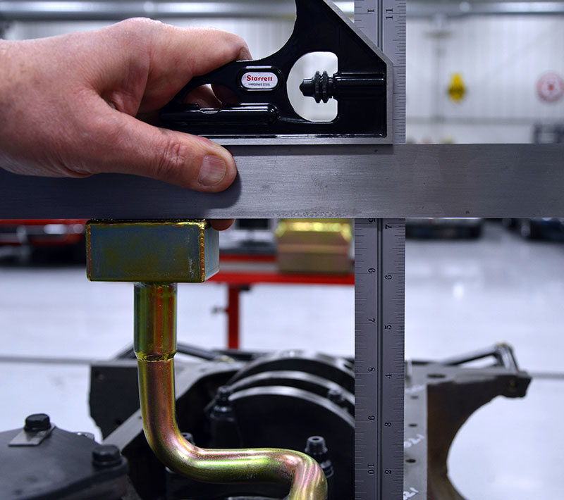
The maximum distance you expect here is a half an inch — 3/8 inch is perfect and a quarter inch is cutting it just a bit too close, particularly on a steel pan with little or no strengthening beads rolled into the floor sheet metal. Can you get away with a quarter inch? Probably (maybe?), but I’d probably weld legs onto the pickup to physically hold it off the pan just to be sure it didn’t pull the floor up into the suction and shut off the flow. I’d say a quarter inch will work with an aluminum pan, which is made of heavier material and stiffer, but with a steel pan I’d be nervous.
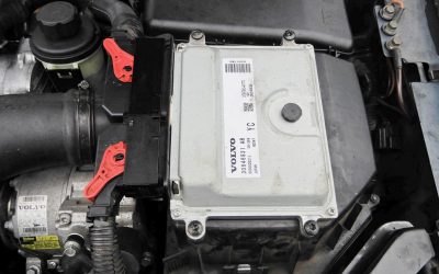
The first order of business is the drive end of the pump, which for most V8s is located at the opposite end of the distributor, driven by the distributor drive gear via the camshaft. Thankfully, the newest generations of engines have long since lost the distributor and the oil pump drives associated with them and are driving the oil pump directly off the crankshaft, either at the nose or from a chain or gear arrangement. This is far more desirable in that it increases pump speed and the mass of the entire reciprocating assembly now driving it is better able to absorb any hydraulic loading variations.
For now, let’s just talk about wet sump, distributor-driven oil pumps. To begin with, it’s not uncommon to adjust combustion chamber volume by milling the heads, and doing so lowers the distributor in the block. So, the first order of business is adjusting distributor depth to accommodate any change in installed depth caused by altering overall head/intake mounting heights. This is particularly important to check if you’re not the first builder, or if you’re freshening up an older engine that’s been in service for many seasons. Before we jump into this, let’s talk about distributor drive gears because there’s no point in continuing until we have the right gear made of the correct materials mounted on the distributor.
Gear materials

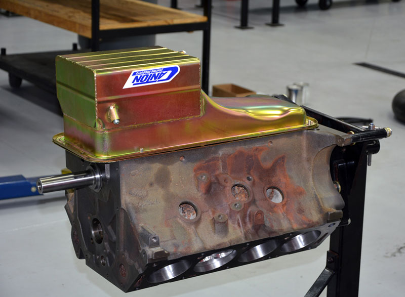
There might be a few non-believers out there, so I included a photo of a restoration engine that came in with no oil pressure — a 427 tri-power big block Chevy is not a good candidate for low oil pressure, much less NO oil pressure! The pickup was right on the deck and the pan got a bit of a dent, and guess what? You can see the witness mark in the pan floor where the pickup ran hard aground and basically sealed off the oil pump suction. Fortunately, there was no engine damage and she lives to roam the streets again, terrorizing children and little old ladies alike.
Cams come in cast iron, ductile iron and steel, and some steel cams are now supplied with pressed-on iron cam-drive gears as an option. One of the big issues with driving an oil pump with the distributor is the loading on the gears. The cam and distributor gear are both relatively small, and high-viscosity engine oils impart quite a load on these gears, particularly when cold, which can result in high rates of gear wear or failure. If you end up using a bronze distributor gear, it’s not uncommon to replace them once a year due to wear, and that’s one reason I’m not a fan of them. Where’s does that material end up? What does it do to the bearings on the way to the filter? It’s the same reason I dress the ends of the valve springs — that sharp tang rotating on the seat and on the retainer is grinding off fine particles that circulate throughout the engine and I like avoiding that whenever I can.
If you’ve ever hand-primed a cold engine with an electric drill you know just how much force you have to counter once the pressure comes up. If you let go of the drill it’ll wind up and smack you stupid on the next trip around. Which brings up an important point: On most engines, no provision is made to pressure lubricate the distributor drive. Where you can, when you can, if an oil gallery or gallery plug is nearby, it’s a good practice to drill a .020 in. hole in it to spray the gear interface with oil, particularly if you’re running high-volume or high-pressure pumps. This keeps gear wear to a minimum and wear swarf out of your engine. Once damaged, the cam can only be replaced, unless it’s equipped with a press-on gear, but that still requires that the cam be removed and shipped off for repair.

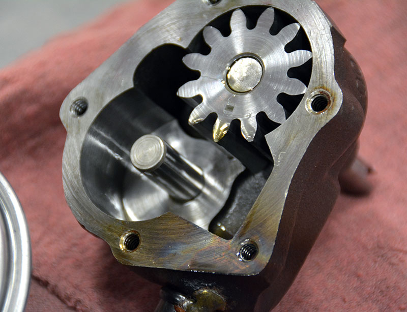
You’d think that a subsystem that runs completely submerged and surrounded by oil would pretty much be failure proof, wouldn’t you? Sadly, this is hardly the case. Here are a couple of examples of things to think about. The rotor shows you what happens if you don’t change out your engine oil before wintering over. Combustion byproducts are corrosive and over time they produce this rusty pitting on everything, including cylinder walls, camshafts, oil pump members and most internal engine surfaces. If you don’t routinely take your engine apart over the winter to freshen it up, at least bring the engine up to full operating temperature and drain the crankcase and filter and put fresh oil in for the winter. It helps to “pickle†the engine with outboard engine fogging oil as well as pulling the plugs and leaving them out for the winter. Resist the urge to go out and start it up… just put it to bed and come spring pre-oil it just like a fresh build, start it up and prep it for the season ahead.
There are four materials available for use on the distributor through several sources: the stock cast iron gears, aluminum-bronze gears, Melonized steel gears, and composite gears. Each material has its application, with cast iron reserved for stock or near-stock use and only on cast or ductile iron cams. Bronze gears are compatible with steel cams, but not with cast iron or ductile iron cams. While bronze may work for a while on cast or ductile iron, service life will be shortened. Composite gears (made of carbon-poly materials) work on any cam material, but are not the best choice for high-volume or high-pressure pump drives. In fact, they are specifically not recommended for those applications by some manufacturers. Melonized steel gears are approved for use on all cam materials and are the first choice for most applications where high-volume and high-pressure pumps are used. I’ve been using them exclusively for some time with no failures to date, but some builders report that they’ve had some early issues with wear. There are some billet steel applications that recommend bronze gears for use with high-volume high-pressure pump drives, so always consult with your cam grinder and get his or her recommendations — never be afraid to ask the question if you’re uncertain. It’s always better to ask what someone might think is a dumb question than it is to make a dumb mistake that could cost thousands in damages. Ego is a damn poor reason to not do your due diligence.
How deep?

The cracked drive gear is a pretty unique failure — it’s the only one I’ve ever seen. I don’t know what went through this pump to cause this break, and there really wasn’t any tell-tale on the pump elements, so I’m guessing this is just a fatigue failure caused by a manufacturing flaw.
To get distributor depth right on engines that are modified for racing, distributor makers offer units with adjustable stop collars so that you can set the installed depth to your application. The three critical measurements to check are the drive gear engagement, backlash, and the oil pump drive rod engagement depth. Using a marking compound of your choice, and while applying counter pressure to the distributor shaft by holding onto the rotor, rotate the cam, remove the distributor and read the marking pattern. The drive pattern should be centered on the gear vertically and you should have a few thousandths of an inch of backlash. You should have some vertical movement in the oil pump drive shaft as well; it can’t be locked up between the distributor and the pump input without doing damage. A good starting point is about .030 in. vertical movement, followed up by reading the gear pattern. It’s the pattern that’s most important to set first; you can always change, grind, or modify the oil pump drive rod to get the end play you need between the distributor and the oil pump. Driving the distributor takes nothing, but spinning the oil pump can require considerable effort, and the hydraulic load can be severe enough under certain conditions to introduce timing chain upset, so get those gears centered and keep your backlash on the tight side of spec to minimize whip and scatter.
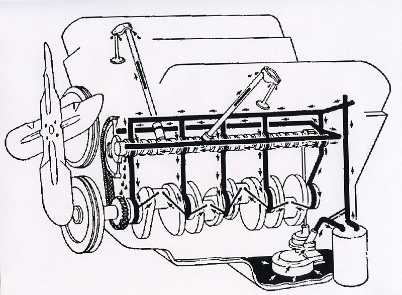
For every engine there’s an oiling map. It’s a circuit through which oil is delivered to the various parts needing it. In stock-block applications, that map is rarely the first thing the engineer designing the block thinks of, and the location or efficiency of how the oil is delivered to the most highly-loaded components is an afterthought. I suggest that you physically check and map every engine you build so you know where the oil goes and how it gets there and what detours it takes before reaching the crankshaft. Remember that every component it passes before it gets to the crank is a leak, and that pressure and volume are dropping all along the way.
If you don’t have an adjustable drive collar and need to move the distributor up simply cut shims from nylon sheet and install them under the distributor mounting flange as needed to move the distributor up. Moroso actually makes shims for Chevy engines and there may be others for different makes out there that I’m unaware of, but you can make them in-house with a gasket cutter set and nylon sheet available through any of the industrial supply houses.
")
Racing engine blocks are specifically designed to deliver oil to the most heavily-loaded parts first, which are the main and rod bearings. Study your application and decide if and where you can restrict oil feeds that rob volume and pressure from your reciprocating assembly, particularly if you are building a lot of power in a stock-block application. Every stocker has weak spots, so do a bit of research and find out where those weak spots are and see if anyone is making parts overcome those inherent design flaws. (Courtesy Dart Machinery.)
The next thing to look at is the depth of engagement between the pump input and the drive shaft that connects the distributor to the drive rod. The oil pump intermediate drive rod should be as large as you can get into the allowable space and made of the best materials available. ARP, Moroso, Manley, Crane, and many other companies offer a variety of extreme-duty oil pump drives. Again, block-mounted distributors like those found on many engines such as some Fords and early Mopars won’t have the dimensional variability created by manifold-mounted distributors and cylinder head modifications, but it’s good practice in every case to install and fully tighten the distributor and check to see that there’s some end play on the oil pump drive. It doesn’t have to be a lot — anything around .010-.050 in. is fine — it just can’t be bound up. Measure the drive rod engagement depth and make sure you’ve got as much as you can get on both ends so that the load is distributed over as much area as possible. There are directions on measuring oil pump driveshaft engagement or overlap at MSD, but the short version is that you measure from the mounting collar to the end of the distributor drive and from the manifold mounting surface to the top of the intermediate drive rod, and subtract the two dimensions. More is better!
Now that the wet sump pump drive is sorted out, we can start to look at oil pumps, pans, scrapers, oil control systems, vacuum systems, and other assorted bits.
Stay tuned, there’s more to come!

0 Comments