

Tracking down electrical failures in harnesses, connectors and wherever else they may hide, can be challenging. Fix them right.

Somewhere in this tangled mess is an electrical gremlin that is poised to ruin your day. Time to get your wiring diagram out and track him down.
Every technician that has been on the job for more than a week has found himself beating his head against the wall because of some mysterious electrical fault that just doesn’t make any sense. Even the aged master tech that awes everyone with his almost magical way of identifying a problem by the sound of a small tick or chirp, will still lament not becoming an accountant when facing a broken wire somewhere in the dash harness.
From intermittent radio reception, to headlights that flash with the turn signals, electricity can be the root of some of the most fascinating and mentally taxing issues a technician can face. With the increasing complexity of today’s cars, getting a solid foundation in electrical diagnostics will make you a more valuable technician.
A good place to start is by getting a better understanding of what makes electricity so difficult to understand. Although we don’t yet understand everything about electricity, we know it has some basic rules it has to follow. We can use analogies about how electricity flows like water in a hose. This helps with the basics but will leave you confused with some deeper problems like RFI (radio frequency interference), and CAN BUS wiring.
The vast majority of electrical problems will be caused by a failed part that can be changed. When they’re not, then they will fall into one of two categories; either a circuit is making contact where it shouldn’t, or it’s not making contact where it should.
Experience is the best teacher as always. The more you work with electricity the better you will understand it. You might even consider time spent on the diagnosis as a benefit, like extra time spent in class. However time is money, so let’s see if we can “illuminate†some of the more mysterious problems. The idea is to come to the correct solution and repair as quickly as possible. The bi-directional nature of electricity, intermittent contact, added resistance, poor grounds and using the wrong tool for the diagnostic procedure can all combine to suck up your time and leave you with a headache.
Bi-directional flow
A common frustration in diagnosing electrical problems is not fully understanding that electricity can flow both directions in most cases. This can become a particular problem if there is a short between adjacent wires in a harness or connector.
A wire that should have no voltage with the key off, for example, may be shorted to a wire with power all the time. The electricity can flow backwards, through that circuit and back to a shared source like the ignition switch, energizing all other circuits on that leg of the ignition switch.
Removing fuses to identify a parasitic draw may identify the wrong circuit in this situation, since the circuit being disconnected might be fed backwards through the branch at the ignition switch. This can lead the technician to guess and change out an ignition switch only to discover that the problem still remains.
Unplugging the connector on the ignition switch before condemning it can reveal the error. This example is a bit extreme, but understanding the bi-directional nature of electricity is a must in order to understand and perform advanced wiring diagnostics.
In the example above, stopping at the first fuse that reduces the draw can lead you astray. Take an extra minute or two and go through the rest of the fuses to insure the one you suspect is the only circuit causing a draw.
Intermittent contact
Without good solid electrical contact your wiring system just will not work reliably, yet the slightest glancing touch of a bare wire to ground can cause instant failure. Both sides of this equation must be considered when chasing an intermittent fault.
Fortunately modern ECMs will often indicate if the signal is too high or too low and sometimes even tell you there is a short to power or ground. Unfortunately not all systems are monitored by a control module, and a short to ground inside a sensor looks very similar to a short to ground in the wire harness. This is why it’s important to follow all the steps in the factory prescribed diagnostic chain when it suggests disconnecting the ECM connector and testing the harness for shorts and opens.
Doing a wiggle test, that is, shaking the harnesses while the system is on, is going to be your first go-to test for intermittent contact. Pay special attention for places where a harness goes around a sharp corner or where a missing harness anchor lets the harness rub. Even a rodent having chewed on the wire insulation can lead to intermittent contact that will set a fault code or blow a fuse.
Added resistance

Back probing the MAF signal gives us info directly from the sensor. If the voltage differs from the data stream on the scanner, we know we have a resistance problem in the wire harness or ECM connection. If we can change the data by moving the harness we know where the problem is.
Added resistance in a circuit has been the cause of many gray hairs and thrown wrenches. You might be assuming you have a sensor failure or mechanical failure while looking at the data stream from various engine sensors, but can you trust the information you’re seeing? Added resistance in a circuit will often cause erroneous readings in the ECM.
There are several ways this can happen — loose or corroded connectors, burnt or hot wires, or even some fluid leaks can raise resistance in a circuit. When condemning a sensor or system, it’s a good idea to verify outside of the ECM that the problem actually exists.
For example a P0128 code indicates that the engine isn’t heating up enough and may need a thermostat. Verifying the actual temperature of the cooling system with an infra-red temperature gun can save you the time of installing a thermostat only to find that the ECT PID was incorrect due to a corroded connector or failing sensor. As a rule of thumb, if you can change your data stream by moving a harness or connector, something is wrong.

Parasitic draw problems will bring us right to the fuse block. Pull every fuse, one at a time, and record which ones reduce your excess draw. If it’s more than one, look at the diagrams for what they have in common, especially the “power distribution†diagram.
In case you’re not familiar with the expression “PID,†it stands for Parameter IDentification. This refers to the individual data streams from the ECM reporting the information received from various sensors within the vehicle.
A wire doesn’t have to be completely open to cause significant diagnostic issues. Back probing a sensor connector is a great way to verify a sensor failure, but don’t neglect disconnecting the connector to check for corrosion, loose terminals, or fluid contamination. Any one of these can trick you into changing a perfectly good sensor only to find that the problem still remains. Should you find a damaged or corroded connector, replace it. Pigtails (assembled connectors with terminals and short leads) are readily available from the parts department for most connectors with fewer than 5 pins, and a few are available with more. For bigger failed connectors, like ECM or fuse box connectors, replacing the entire harness may be in order.  Â
Poor Grounds
Some of the most interesting and laughably ridiculous failures stem from poor grounding. A very common example of this failure is running lights that flash with the opposite turn signal. When looking at the circuit diagram, the circuits may seem completely separate. In the vehicle they can share the same bolt grounding them to the body or frame. Should that bolt get rusty it may no longer have a solid grounding connection.
This brings us right back to the bi-directional nature of electricity. If the turn signal can’t ground through the ground wire, it may find a path to ground through the shared ground in the running light bulb. It can then power the running light circuit backwards and finally ground at another running light ground point.
Although drawn out, this example gives a clearer idea of what can happen when a shared ground fails. These kind of failures are often very difficult to pin down; measuring the resistance of the ground side of the circuit with a voltage drop test will often point out a bad ground.
This is even more critical when suspecting a faulty module, like a ECM. One ground with high resistance can skew all the input information for the ECM.
Before replacing any module it is a good idea to test each power and ground circuit, especially if the module displays an internal error. Even if a poor ground connection isn’t the direct cause of the symptom, the added stress on the system could still be the root cause, leading to another failure in the near future. When repairing a rusty ground, solder a new ring terminal and wire brush the mounting location. Clean rust from grounding locations, and then protect them with dielectric grease to prevent future corrosion. A solid ground point must be clean.
The Right Tool
Using the right test equipment for a particular failure isn’t as simple as it used to be. Where we once used probing test lights and analog multi-meters for most problems, we now have a wide range of tools that are far more accurate and safer.
The test light is seldom used in modern vehicles and many tool boxes don’t even carry one. Using an old fashioned test light on a modern computer controlled engine is not only dangerous for the ECM, but also doesn’t usually give any useful information. Should a test light be connected to ground and probe a powered wire from the ECM, the amperage draw of the bulb in the test light may far exceed the capacity of that specific driver in the ECM. The result is irreversible and the need for a replacement ECM.
Even if the circuit you are intending to test can easily handle the load, a simple mistake in wire identification may have you damaging another circuit. The proper tool is a high impedance digital volt/ohm meter. Not only is the DVOM safe for any ECM circuit; it will actually give you useful information like actual voltage and resistance.

This Quest has been crippled by rust. After cleaning the mounting and replacing the terminal on the wire, it’s time to check the rest of the grounds on the van for the same problem.
The graphing multi-meter is a wonderful time-saving tool. Often a circuit failure will happen faster than the DVOM can react. You connect your wires properly and have the correct voltage or resistance reading, yet the circuit is still setting a DTC. The answer is to use a graphing digital multi-meter.
By actually graphing out the voltage or resistance readings, you can see momentary drop-outs or spikes in the voltage that you would never see watching a numerical display on a DVOM. The perfect example is the 5V reference signal. A completely open circuit will be easily seen by either tool, but many small or intermittent drop-outs may require a graphing multi-meter to see.
Connecting a graphing digital multi-meter to an inductive amp probe, you can watch the amperage fluctuations of any DC motor. In a fuel pump or blower motor, for example, you can see irregularities in the pattern that can reveal a potential failure. This is extremely helpful when diagnosing intermittent failure situations when an electric motor is working when it comes into the shop.
Another example would be a suspected starter motor. Excessive amperage spikes or drop-outs can point to a failing starter even if it seems to be working OK. And as an added bonus, the amperage will fluctuate with the compression in each cylinder, in effect, giving you a kind of cylinder balance compression test. If every 6th peak is lower than the rest in a 6 cylinder engine, you might suspect one of your cylinders has weak compression.

The green trace is the voltage on the trigger wire for the starter solenoid and the yellow trace is the amperage of the starter. With a stable pattern, this is what you want to see in a starter test. Can you tell how many cylinders this engine has?
Even with these modern tools it’s still possible and even common to damage the wiring system with sloppy testing techniques. When testing wires it is tempting to use the sharp electrodes that come with the DVOM to pierce the wire casing and take your reading. Often this will result in a damaged wire, either by breaking the copper strands in the wire or by allowing future water intrusion through the hole in the casing.
Another common mistake is to unplug a connector and probe directly into the female side of the connector. This will typically give you an accurate reading but will often damage the connector by spreading the terminal end, making a poor connection when the connector is plugged back in. It may seem nit picky, but causing an electrical fault while trying to find another fault will make your job much harder.
A better way to test the wiring is to back probe the connector with a metal pin. With an inexpensive box of T-pins from the local fabric store you can safely and quickly test almost any connector by pushing a pin between the wire and seal on the back of the connector. Making sure to push the pin in far enough to make contact with the back of the terminal, it is much less likely to damage the wire or connector and doesn’t usually have to be removed until all of your testing is done, allowing for quick switching back and forth between connections. This method also allows testing with the connector plugged in for voltage drop tests and, with extreme caution, supplying external voltage or ground.

This connector was damaged by an eager young technician. By forcing a DVOM test lead into the face of the connector he confirmed a low resistance ground but added more work in having to replace the connector he damaged.
Using T-pins and jumper wires with alligator clips allows for easy and safe testing of almost any circuit, so long as you make sure the pins don’t stick out far enough to make contact with a grounded surface. When back probing more than one wire in a connector it is also important to be sure the pins don’t touch each other unless you are sure you want them to.
An example of when you would short the pins would be with an ECT sensor that is reporting an unreasonably low temperature. By briefly touching the pins together and observing the ECT PID you can quickly eliminate or confirm faulty wiring in the harness. If the temperature reading spikes high you know the ECM is reading the low resistance of the shorted pins, simulating a very high engine temperature. This would confirm that the wires to that point are good and your problem is somewhere downstream of your test point, in the sensor or in the business side of the connector.
Electrical wiring in an automobile is vulnerable to many different failures. Each kind of failure tends to have a specific location where you’re likely to find the problem. With a little logic and testing, finding the issue doesn’t have to be a “needle in a haystack†kind of search.
If you’ve confirmed an open in a wire, a good place to start looking for it is any place that moves. Door jambs, trunk lids and seat tracks are some of the more obvious examples, but also observing how the engine harness moves as the engine strains against its mounts can give you a place to look for a damaged wire. A broken motor mount makes it even more likely that a harness would fail when it moves more than it typically would.
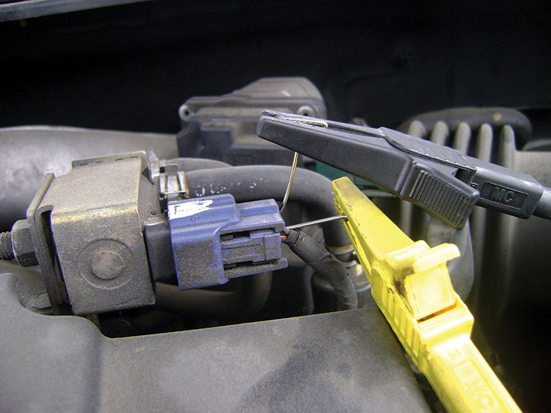
By back probing this EVAP purge solenoid and bending one of the T-pins we can safely monitor the voltage with the engine running and the solenoid in use. This will help to identify intermittent failures as we can test while power braking or even driving down the road.
Should you find a break in a wire at a point in the harness that flexes, don’t splice the wire together where it broke. A better idea is to cut a section of the damaged wire out and make two splices, one well before and one well after the flexing point. A rigid soldered repair is more likely to fail while flexing than a fresh piece of wire. Also, if one wire in a harness at a flexing point has failed, inspect the neighboring wires for fatigue and a possible future failure. When several wires have failed it might be prudent to change the whole harness to be safe.
Above all else, be patient. When you find yourself getting frustrated, stop and think. Check for TSBs, look at the diagrams again, and use a highlighter. Nothing ruins your day worse than realizing you’ve just spent two hours chasing the wrong wire because of a simple misreading of the diagram.
Confirm your repair and take a second to figure out why the failure happened. Wires don’t spontaneously break and connectors don’t corrode by themselves. If you did find a damaged wire or connector, ask yourself “How did this happen?†Often you will find another circuit with the same problem. Electrical diagnosis gives you plenty of ways to mess up, so don’t take it personally. It’s not worth the gray hair.


How can print any document.Help
Hi CastilloReynaldo,
At the bottom of every article is a “Download PDF” link. You can download and then Print each article. Please let us know if you have any further questions.