
We had this unusual case with a 2000 Beetle 2.0L with the 01M 4-speed automatic transmission. This particular transmission is also used in the Golf/Jetta versions and we still see them in service. The “unusual†part to this transmission mystery isn’t the transmission itself; it’s how it ended up at the repair facility.

There is NO possible way a “NEW†harness is in this condition.
Take a walk in my shoes for a while. I’m willing to bet quite a few readers have experienced similar situations, and let this be a warning to the ones that haven’t. Note: I was NOT the interrogator from the beginning.
Credit does go to my compatriots and the vehicle owner. The suffered headaches are mine alone. This incident went from simple to undesirable but many lessons were learned (we hope).
Day 1
The customer drove the Beetle to the facility. The decision was to believe the shifting was defective so why not just inspect and scan BEFORE this Beetle went on the road. In the service bay, we performed a primary diagnosis with the complaint, “It shifts from first to second but most often does not shift into third or fourth.†The customer added into the conversation during the initial phone call, “I rebuilt the valve body, used cleaning solutions such as mineral spirits and refilled the transmission and added a new solenoid harness.â€
So what did we see? A BIG transmission leak on top on the case, dripping on the floor with a few nuts and bolts missing. What caught my eye were the missing bolt that held a two piece bracket holding speed sensor G68 and the solenoid harness together. This transmission was NOT going to be road tested in this condition. Faults are as follows for the ECM and TCM but a complete autoscan was also performed and saved.
|
|
||||||||||||||||||||

Altitude Correction
One of the very first pieces I wanted to look at is Altitude Correction. Since we were close to sea level, a small minus number was expected.
-8.6 percent was not expected. With other tested proof, the true value should be close to -3.1 percent. The value in the ECM is more than twice what it should be.
At the same time, we looked at running parameters for the engine up to normal operation temperature. In view are groups 001 and 002 for Mass Air Flow and Lambda Control.

Have a look at the earlier complaint 16486 for MAF; Lambda control is skewed to a large minus number but MAF is reasonable for the moment.

Simple Explanation: Pin 1 is the power supply to solenoids 1,2,3,4,5,7, and the temperature sensor.
Pin 12 is the temperature sensor signal return.
Recording these parameters, we moved onto the transmission to find the leak (washed it) and viewed the data at normal operating temperature. Oddly, when looking at the transmission temperature sensor, the value would quickly toggle between 80 and 110 degrees C. Remember the missing bolt that held G68 and the solenoid harness together? Before that was re-attached, we looked at the solenoid harness (of course the retaining clip was missing).
We cleaned the harness on both ends and used a high quality synthetic grease to re-assemble the harness and bracket with a new bolt. Do you think this may cause the unusual transmission temperature readings at idle? Definitely for sure and if the transmission reads the temperature hotter than it should be, this transmission will definitely go into limp mode for self survival. There is so much more to this.
What about the leak? The solenoid harness is a little “difficult†to remove because the transmission cooler sits on top of the harness (hiding it) and clipped in two positions. The assumption was that the owner of the vehicle lifted the cooler and didn’t notice the two lower sealing o-rings. We found the missing one on the floor after cleaning the oil. Assumption correct!
Day 2
Now we need 4 o-rings and the coolant flange that was leaking and noticeably cracked. After installation, adding coolant and topping off the transmission fluid level (has to be done via scan tool at 30 degrees C and watching the spill port), I think we’re ready for a road test. But let’s try it on the hoist first. Assumption incorrect! The original fault didn’t return but a new TCM fault was recorded and definitely in limp mode!
Day 3
The story moves on, but remember that bracket/support for G68 and the transmission solenoid harness? Can this get any better? Of course this can, and why not lead ourselves up a path while consuming extra caffeine with cheese cake, strawberries and blueberries? As Marie Antoinette once remarked when she was told the population was revolting and hungry, “Let them eat cake.â€
The uncertainty (mea culpa) was no road speed recorded (TCM Scan) on the hoist and, on the next round of diagnostics, we chased our tails with the following images.

This fault was never recorded earlier and is immediate. The following images lead us to believe that the transmission was missing “road speed.â€
Chasing the road speed signal to the TCM added more coffee and more cake. The driver’s side transmission mount requires removal and G68 is on order. Bench testing the original part, we found an open circuit. I need to interrogate the vehicle owner in detail. Vehicle speed sensor G68 voltage can be viewed at TCM group 002 field 4.
The speed sensor G22 attached to the transmission case (instruments, Comfort Control, air bag, ABS and ECM sensor) does NOT provide road speed for the TCM.

The fourth field is road speed. It is the output shaft speed at G68. With an open circuit and since the output shaft speed is not being read, the transmission sets limp mode, harsh gear engagement and starts out in 2H while in D with the wheels spinning at about 10 mph for a short period. The view is TCM group 004, field 4 and also found at TCM group 003 field 1.
 the speed signal returned and so did the correct voltage in at the TCM, group 002, field 4.")
With the new speed sensor in place (removing the mount) the speed signal returned and so did the correct voltage in at the TCM, group 002, field 4.
It would appear that this transmission may finally work.
Not quite and not so fast. While we were chasing this issue, there were a few oddities found while we looked deeper. One was the debris at the outer engine cowl and inner cowl where the dust and pollen filter resides. Additionally, and still looking under the battery tray and the inner cowl, there was some tape on the harness that VW NEVER uses. This tape is wide and appears to look like stretched, thick, self adhesive rubber. Someone was there before and looking for a problem.

This image shows the correct name and position of speed sensors.
G22 – Instruments road speed – NOT connected to the TCM
G38 – Transmission Input shaft speed Min. 0.8 K Ohms Max. 0.9 K Ohms
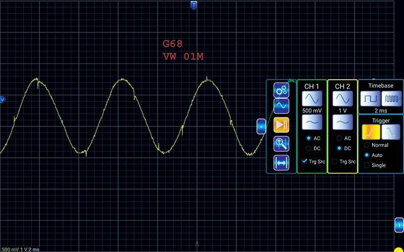
G68 – Transmission Output shaft speed Min. 0.8 K Ohms Max. 0.9 K Ohms
The Beetle was finally assembled and tended to shift properly on the hoist. All fault codes were deleted and the road test began, uphill being the first choice.
This transmission ended up with a serious flare from second speed to third speed and was able to repeat it every time. The transmission was shifting throughout the entire range with no faults recorded, except for that flare.
The customer arrived the next day for a detailed discussion.

Sometimes a good deal isn’t such a good deal. Sometimes sitting for a few months can be a while longer then what the truth really is, meaning a complete lack of service.
Day 4
- The customer’s story in point form:
- Beetle was purchased and belonged to someone’s father-in-law.
- This Beetle sat for a few months (he was told).
- Customer mentioned that this “flare†was noticed previously but experienced poor or non shifts regularly (the hint).
- Customer did his own research and purchased a new eBay solenoid harness.
- Customer purchased a “performance†valve body kit (now we know).
- Customer had a family member record the disassembly (smart thinking).
- Customer lifted the transmission cooler (the leak).
- Customer did NOT set the manual valve (oops).
- Customer filled the transmission.
- Customer power washed the transmission case (green monsters).
After the discussions, and at this point, the customer drove the car and noticed all shift points and the 2-3 flare.
|
Lesson 1 |
Get details from the customer and persist on getting all the details. |
|
Lesson 2 |
All management and staff must be aware of the “value†of all details. |
|
Lesson 3 |
Ask the customer where the “research†was found. |
|
Lesson 4 |
Never assume. |
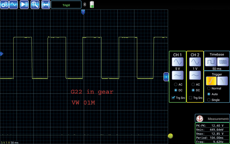
Engine running, in gear and at idle speed.
When the customer is attempting to save a few dollars and when “researching†these types of problems, the people that post these “magic†solutions should also mention replacing a valve body, installing a performance kit or replacing solenoids with a harness will never repair a leaking clutch. That was lesson 5.
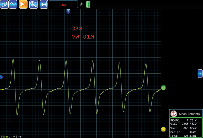
Engine running, in neutral, applying slight throttle will change the amplitude.
If the original or new owner keeps driving this transmission in limp mode, expect internal clutch wear and slippage over time.
This is the one the transmission uses to measure road (vehicle) speed. Measured in D at idle.
In the background and eating cake, I made sure the VCDS label was updated, detailed and proven in a very serious manner to make sure these “assumptions†would at least be put to rest. Ross-Tech users will have this file on their next update. Two links are provided for those moments where the harness is a cause for G38 and/or G68 errors. The TSB details the repair. In this case, the TSB does not apply.
Resistance readings and parts replacement is one thing, but getting to scope the sensors to watch their behavior is completely different when testing these three different speed sensors. Since I was in there, still had some cake and had access to a “quick†scope, the following images should look “correct†at the three speed sensors and should be performing correctly.
Marie Antoinette ran out of cake and so did I. On a side note, the MAF question, Lambda Control and Altitude Correction issues were repaired with a MAF sensor that fit the correct year, make and model.


0 Comments