
Vehicle emissions control devices have been in use for more than half a century. The crankcase ventilation system was one of the first emissions systems used on cars.
Every modern vehicle on the road has a crankcase ventilation system. This is a critical system used to contain blowby gasses during engine operation. Blowby gasses from combustion can cause engine damage if not properly vented from the crankcase.
Positive Crankcase Ventilation
To control these gasses, most manufacturers use positive crankcase ventilation (PCV). This system is designed to keep a slight vacuum in the crankcase. The vacuum pulls the crankcase gasses out of the engine and recirculates them back into the intake to be burned. On older vehicles, these gasses were vented into the atmosphere. By not venting crankcase gasses externally, vehicle hydrocarbons and emissions can be greatly reduced, with no detrimental effect on engine performance or fuel economy.
The positive crankcase ventilation valve is actually a relatively simple mechanism. By using a lightweight spring design behind a rubber diaphragm, crankcase vacuum can be controlled. Crankcase vacuum is at its highest when idling or under decel. To control this, the PCV valve limits flow under high vacuum. At higher engine speeds, less crankcase vacuum exists, allowing the PCV to flow more crankcase gasses into the intake.
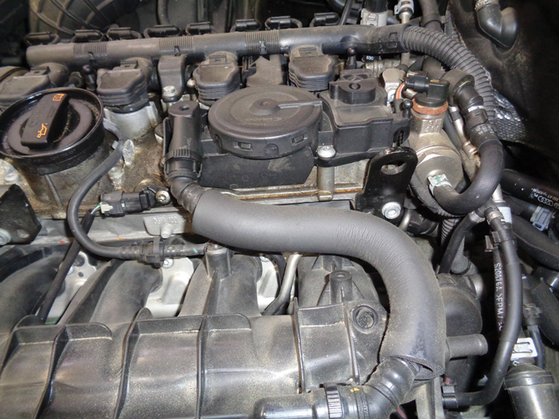
With forced induction engines, such as the Audi 2.0t, the crankcase ventilation system has a lot of additional pressure to deal with. The crankcase breather valve is a high-failure item on modern Audi engines.
Too much internal pressure can cause several issues. Seal damage is quite common on Audi vehicles from a failed crankcase ventilation valve. The rear crankshaft seal, unfortunately, takes the brunt of the damage on Audi engines. Increased engine oil consumption is also an indicator of a failing valve.
Much of this oil ends up in the intake tract, which only makes things worse. On Audi turbo vehicles, this means the intercoolers may have excessive oil in them. The sensors on the intake can also suffer from oil contamination. Most commonly damaged are MAP sensors, if equipped. Additional oil in the intake tract also has the effect of increasing carbon buildup. The direct injection engines already have carbon buildup issues, and this can quickly exacerbate the issue.
Excessive crankcase underpressure can cause a multitude of issues as well. The most common symptom of a failed PCV valve on an Audi vehicle is rough running or random misfires. Seal damage is quite common from excessive vacuum as well. In extreme cases, the engine may not even start or continue to run after excessive vacuum builds.
A quick check for a failed PCV valve is to try to remove the engine oil cap while the vehicle is running. Under normal operations, the oil cap is easily removed. The engine will stumble after removal; this is normal. If the PCV valve fails, the oil cap is almost impossible to remove. This is an example of the extreme vacuum the crankcase may contain. Whistling from the engine may also be heard with a failed PCV valve. Don’t blame the turbo!
Audi vehicles are generally good at storing faults for crankcase ventilation issues. However, the codes stored may not directly fault the PCV valve. Faults range from fuel trim bank faults, idle higher than expected faults, as well as random misfires. It’s important to check fuel trim values in measuring blocks. This will lead toward a definitive diagnosis.
If using a factory based scanner, access group 32. These measuring blocks reveal fuel trim values stored in the engine computer. Additive and multiplicative fuel trim values are the primary values the ECU uses to control and monitor proper fuel injection. Without the correct amount of air entering the engine, the fuel injectors will not be able to determine how much fuel to inject.
Additive fuel trim values are the primary concern when diagnosing a suspected failed PCV valve. This is the fuel trim value at idle. Proper specification is +/-10 percent. The higher your additive value, the more fuel is being injected to compensate for an air mixture that is too lean.
False air leaks and failed crankcase vent valves are the primary culprits here.
A failed PCV valve is most obvious at idle due to higher engine vacuum levels while idling. An excessive negative additive value indicates a rich condition at idle. This can usually be traced to leaky fuel injectors. A good way to test for a failed valve is to clamp off the primary line leaving the vent valve. This should be the large line leading to the intake manifold.
With older engine models, use coolant line clamps to cut valve flow. On newer engine models, you may need to use vacuum caps to seal it off. If additive fuel trims pull back closer to specification with this line clamped, you definitely have a bad vent valve. Do not drive the vehicle with the line clamped! Use this only for testing in the bay.
Multiplicative fuel trim values are used to control fuel injection under load while driving. Specification for multiplicative values should stay under +/-10 percent as well. An extremely high value, such as +20 percent, indicates the computer is adding fuel to adapt for a fuel mixture that is too lean. This is generally a vacuum leak causing unmetered air to enter the engine. On older 1.8t engine Audis, the MAF or mass air flow meter was a common culprit for high multiplicative values.
Multiplicative values in the negative indicate too much fuel is being injected under load. Often fuel control issues are the root cause here: leaking fuel injectors, fuel pressure too high, etc.
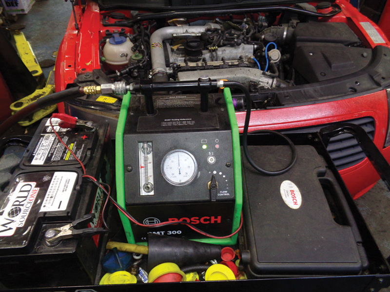
When diagnosing a suspected issue with the crankcase ventilation system, an automotive smoke machine is an absolute necessity. These PCV systems must be completely leak-free to operate properly. Any small leak or damaged breather line will affect fuel trim values. Due to the complex routing of breather lines and connections there are many possible failure points. A smoke machine makes it easy to pinpoint leaks in almost any system.
Hook the smoke machine to the intake boot or any accessible point on the intake manifold. This lets the smoke travel through the entire intake tract as well as the vehicle’s crankcase. During inspection, pay close attention to any lines or connections that appear particularly oily or damaged. Even small leaks can cause a check engine light!
Use of an inspection mirror under the intake manifold may be necessary to locate leaks. Don’t forget to inspect ALL of the lines fed off of engine vacuum when looking for leaks. Brake vacuum lines are notorious for degrading as well as the power brake booster.
The booster can leak engine vacuum causing a false air leak with no appreciable braking loss. On new Audi engines, many of the breather lines are constructed from a corrugated plastic line. These are quite thin, and the retaining clips become brittle with age. During inspection and testing, if you have to remove these lines, be cautious. A preliminary spray with penetrating oil on the retaining clips will aid in safe removal.
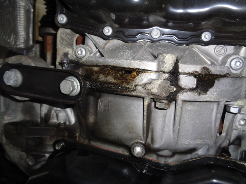
Don’t forget to inspect engine seals for leaking during the smoke test. Yes, the rear crankshaft seal commonly leaks crankcase vacuum and oil. In most cases, the rear main becomes completely separated, allowing extensive unmetered air to leak past.
On most Audi models, it’s possible to see smoke leaks from the passenger side upper bell housing area after removing the side access cover on the transmission. Oil leaks from below are also a dead giveaway at a failed rear crankshaft seal. It’s also possible to spray carb cleaner into the bell housing while the engine is running to watch for fuel trim changes to determine a leaking rear main. But this is not recommended. Smoke testing is much safer and more reliable. The rear main seal is a common failure. Aftermarket upgraded solutions are available for the rear crankshaft seal.
Always replace the crankcase ventilation valve if a rear crank seal is being replaced. This is the number one culprit for rear main seal failure on many 2.0t Audi engines.
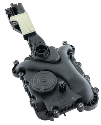
On many Audi VR6 engine models, the crankcase ventilation valve is built into the valve cover assembly. If the valve diaphragm has failed, it will leak through a weep hole that is visible in the corner of the valve cover assembly. These will show smoke leaking out as well as making a whistling sound while running.
On the VR6 engines, the entire valve cover must be replaced to remedy a bad crankcase vent valve. This requires intake manifold removal as well as fuel rail removal on direct injected engines. Always replace intake manifold gaskets as well as fuel injector seals. You do not want to have a damaged fuel injector o-ring on a direct injected engine. It’s a big job to fix the crankcase valve!
Many 2010-2016 V-6 models suffered from crankcase valve failures, and updated valves have been implemented. These commonly set rich faults when they fail. On the Audi 3.2 V-6 engine, the crankcase ventilation valve is located deep in the valley under the intake manifold.
Due to space constraints, the valve assembly is quite literally buried. It requires intake manifold or supercharger removal, followed by fuel rail removal, to fully access the crankcase valve. In V-6 engines equipped with variable intake runners, these must be removed as well. When re-installing, be sure to clock runner position correctly and run basic settings on them to verify proper function.
Secondary Air Injection
Air injection has long been a part of many vehicles’ emissions systems. The secondary air injection system plays an important role in modern Audi vehicles emissions systems. In the system used by Audi, an electrically driven air pump is used to supply fresh air to the exhaust stream. This is primarily used when the vehicle starts up, at which time it runs rich, producing more emissions until reaching normal operating temperatures. The air injected into the rich-running exhaust stream helps to quickly heat up the catalytic converter to operating temperature, which lowers hydrocarbon emissions.
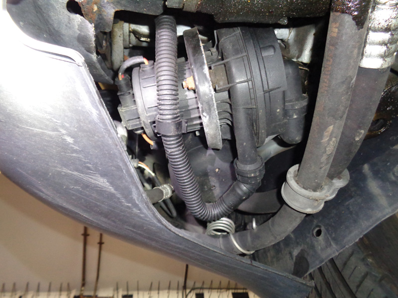
The secondary air injection system relies on few components for proper function, the air pump being the primary workhorse of the system. Air pump location varies by engine model but is most often mounted in the lower forward fender area. Air pumps require a clean air supply and often have an intake tube going to the air box. This line must be connected to ensure good air flow.
In many higher-mileage Audi vehicles, the air pump eventually fails. Often they suffer from water ingress from broken inlet or outlet lines and rust or short out internally. On many air pumps, the casing begins to separate with age. This allows air to leak out of the pump casing. The pump may sound fine when listening but is not producing enough pressure for proper activation.
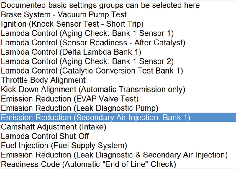
The secondary air pump can be activated via scan tools in Basic Settings group 077. After clicking Go, the air pump should be audibly heard. Always check for power at the air pump as well. If the air pump seizes, often the fuse goes as well.
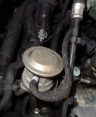
The check valve, or combination valve, also plays a role in secondary air injection. It is used to control air flow from the air pump to the exhaust stream. Without the combination valve, exhaust flow would be allowed to travel up into the air pump housing.
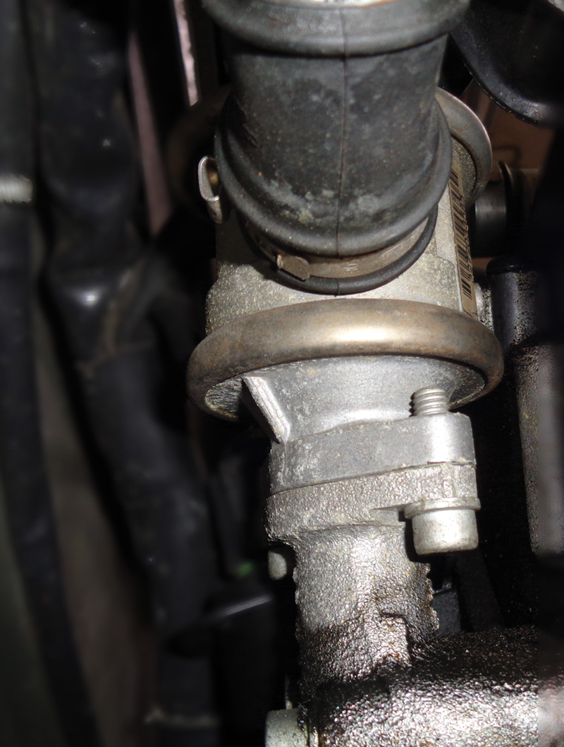
This happens occasionally when check valves become seized in the open position. More often when the combination valve fails, it becomes seized shut, preventing air flow into the exhaust stream. This is usually caused by rust buildup on the check valve from water intrusion. These valves are exposed to extreme heat from the exhaust system and can damage other components if problems arise.
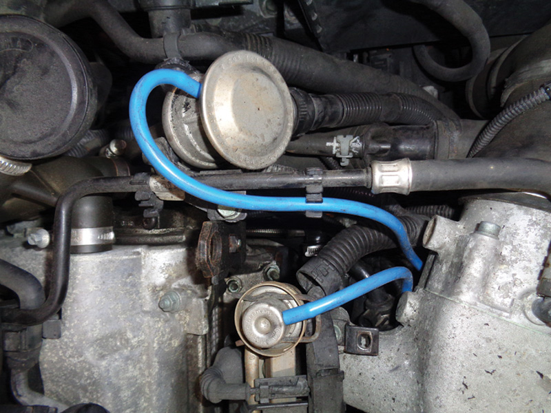
Most combination valves can be tested by using a hand-held vacuum gauge. Vacuum leaks are the enemy here. Very small vacuum lines feed the check valves. On models with electronic combination valves, activation through scan equipment is necessary.
Always thoroughly inspect air injection lines for damage. This system is exposed to extremes due to exhaust heat and suffers from it, creating brittle plastic lines everywhere.
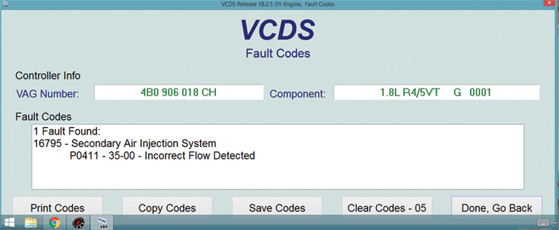
The ECU relies on input from oxygen sensors to determine proper air pump activation. If it is unable to see a change in oxygen sensor voltage quickly enough during the warm-up phase, it may set a fault for secondary air. This means the primary oxygen sensor must be working properly to identify voltage fluctuations. A lazy oxygen sensor may not always set faults immediately, making accurate diagnosis more difficult.
In most engine applications, the secondary air ports must be built into the cylinder head assemblies. This is due to packaging limitations as well as the necessity to provide maximum efficiency in the air injection process. Keeping the air injection ports as close to the exhaust manifold ports as possible ensures even temperature distribution.
The biggest problem with moving the secondary air passageways into the cylinder head is the possibility of passageways becoming blocked. Because exhaust gasses are able to travel through secondary air ports in the head, they eventually become clogged with buildup.
This has become an issue on the 3.2 and 3.0 V-6 FSI engines with air injection. Blocked air ports are also an issue even on lower mileage engines, as low as 50K miles. Common faults stored are P0491, 0492, secondary insufficient flow b1,b2.
It’s possible to run a readiness monitor to test the secondary air system for proper function on these models. Via scan equipment, enter the Engine Control Module, then Basic Settings. Test 77 under Basic Settings will run the air pump monitor. If the air pump and connecting hoses both appear to be functioning properly, the ports in the cylinder are likely clogged and require cleaning.
Secondary Air Ports
Cleaning clogged secondary air ports is not a quick job. Unfortunately, to even complete the cleaning process, specific tooling is required. Audi recommends a special power washer that uses regular water for cleaning and specific right-angle spray heads to directly clean the air ports. The power washer Audi recommends operates at more than 1,500 psi. Be careful!
Secondary air ports can be accessed at the front of the engine by removing freeze plug covers that block off the air passageways. These can only be accessed after putting the vehicle’s front end in service mode and removing the coolant transfer pipe and water pump pulley on the V-6 engines. By running the power washer wand down each air port, the carbon buildup will be washed away.


0 Comments