
As discussed in the last issue, oil is the lifeblood of the internal combustion engine (ICE), the cooling system is a close second. Loss of oil pressure for any reason is the first smell of death. Most equate loss of oil pressure to low oil level, a common cause of low pressure in the history of the ICE.
In the last issue the complaint of “low or no oil pressure†was addressed and blockage, or partial blockage of the oil pressure pump suction inlet was explained. Once the blockage issue is addressed, remedied or verified, the technician must then look into the 9A1 pressure and control systems. In order to understand better how the system operates, a quick look back at Porsche oil systems of the past will help illustrate the progression, problems and solutions.
Porsche air cooled six cylinder horizontally opposed boxer engines all employed “dry sump†type oiling through 1998. Simply put, this eliminated the oil stored inside the engine, usually in a sump under the crankshaft. In a wet sump engine the whirlwind of air and misted oil that slings from a crankshaft at road speed adds heat to the oil, robs the engine of power and aerates the oil, something like whipped cream. This decreases fuel mileage and increases emissions.
In the dry sump system the oil scavenge pumps and pressure pump work in tandem.
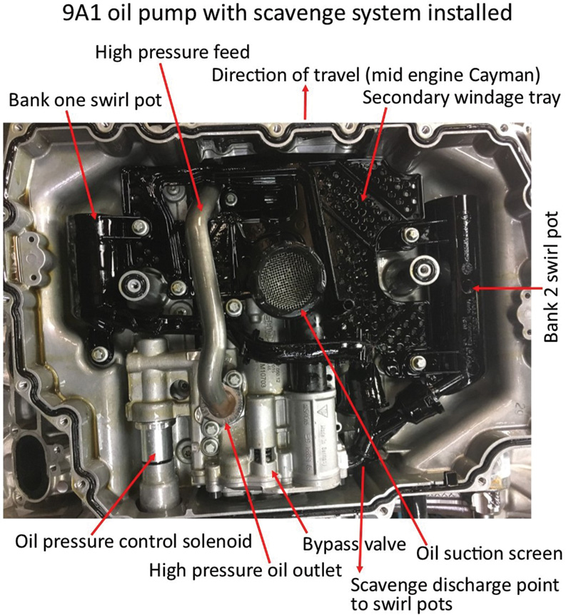
Later, larger displacement air-cooled Porsche engines used three stage pumps, and the turbocharged engines use a four stage pump. The scavenge section or sections of the pump remove the used oil from the dry sump. Note this area of the pump is attached to the oil suction tube and screen. Just above and offset is the splined drive shaft that attaches to the ½ engine speed driven intermediate shaft. The pressure part of the pump is the smaller section to the left.
The hot, dirty oil is then routed through hoses and hard plumbing, first to the oil thermostat and then either back to the tank or through the air-to-oil heat exchangers (radiators). The cooled oil then passes through the oil filter, then returned back into the storage tank located inside the right rear quarter panel. The cooler, cleaner oil is then stored in the oil reservoir until it is recycled back to repeat the cycle over and over.
When the oil is sucked from the reserve tank into the main pressure pump, it performs like a single stage pump in a V8. The pump runs at half engine speed, and oil pressure is governed by the engine speed and the oil pressure relief valve. When oil is cold it produces higher pressure which can spike and damage components like the oil filter and the oil cooler. A spring loaded bypass valve is incorporated into every ICE to prevent pressure spikes. The bypassed oil is returned directly to the sump where it is drawn back into the scavenge pumps once again.
Basically, bypassed oil is wasted energy to pump the oil in the first place, then spending or wasting more energy to draw it back into the scavenge pumps. This, of course, is not a way to get better fuel mileage or reduce emissions. The typical V8 style wet sump system uses gravity as its scavenge system where the used oil finds its way eventually back down to the oil pan.
Dry sump type oil systems have many advantages and some disadvantages. Keeping score? On the plus side we have:
- Liquid oil is kept away from rapidly moving parts, like the crankshaft, connecting rods and pistons. Oil that has done its lubricating job must be evacuated; otherwise it builds unwanted heat and the dreaded aerated oil from the sump.
- The scavenged oil can be cleaned and cooled without loss of oil pressure to the crankshaft and bearings.
- The storage tank can be built and located to enhance cooling.
- Air/oil separation is achieved by gravity. The air simply floats to the top and out the vent system.
- The reservoir and the oil in it have weight which can be moved within the vehicle to a lower point or to balance the chassis for optimum vehicle handling.
On the minus side of dry sump systems:
- Multiple pumps must be employed vs. one single pump.
- Weight is added to the vehicle and this hurts fuel mileage and increases emissions.
- Additional components for the dry sump system cost more money to produce and install.
- Emissions are further increased when venting the oil tank to atmosphere.
All in all, if the system is maintained, dry sump systems are nearly bulletproof and the way to go, until… the bean counters tell you that your tiny German company will be no more, unless they put a water jacket around those naked cylinders to reduce noise and emissions. And, oh, by the way, you now will need to mass produce the powerplants. Enter the Japanese. Can you think of a better culture to save the mighty family-owned Porsche company? They came in as consultants in the 1990s and kicked off a new era of mass production.
Enter the M96/97 based flat six water cooled 911 engine in 1999. It utilized the same layout, same firing order but eliminated air cooling and dry sump oil systems. It kept the ½ speed “intermediate shaft†(more on this in later chapters) to drive the camshafts (four cams now vs. two) and the engine oil pressure pump.
Porsche tried to incorporate the dry sump idea into a wet sump engine. This led to oiling problems with the aerated oil from the cylinder heads being directed into the oil pickup area and starving the main oil pump of clean, non-aerated lubricant. Now use that engine in high G force situations like autocross, track days, racing or even spirited street driving and the situation is exacerbated. Many solutions have been entertained to keep these first generation liquid-cooled cars running and reliable.
Many of the solutions were brought out in the second generation engine, or 9A1 configuration, that has been in service since 2009 and is currently still in production including in the GT3, GT3RS, GT4, all Cayman and 991 models including the Turbo. As these modern engines, like most other engines manufactured around the world, they prioritize emissions, fuel economy and cost of manufacture. Specific power output can now be over 125 horsepower from every liter of displacement. The oiling systems have been stretched to their limits as they now provide hydraulic power to operate camshaft timing, camshaft variable valve lift, and even high pressure fuel pumps.
This increased demand had to be met, and it could not have been achieved without electronic controls. That demand led to a computer that can sense load requirements and â€dial in†the optimum fuel and ignition timing, advance or retard the cams to produce max power at lower rpm’s, and still have good fuel economy.
What happens in the older engines when the oil pump gives too much pressure? It utilizes the oil bypass system; it just dumps the hot and now hotter oil back into the sump where it sends aerated oil back to the pressure pump, all of which is a waste of fuel and heat.
Now, with computer controls, the ECU can combine all of the maps and programs with the input signals and determine the exact load on the engine internals and command a response from the now variable oil pump to increase or decrease pressure. With this design there is no waste, and this, in turn, results in better fuel economy, lowered emissions, less heat, and more power.
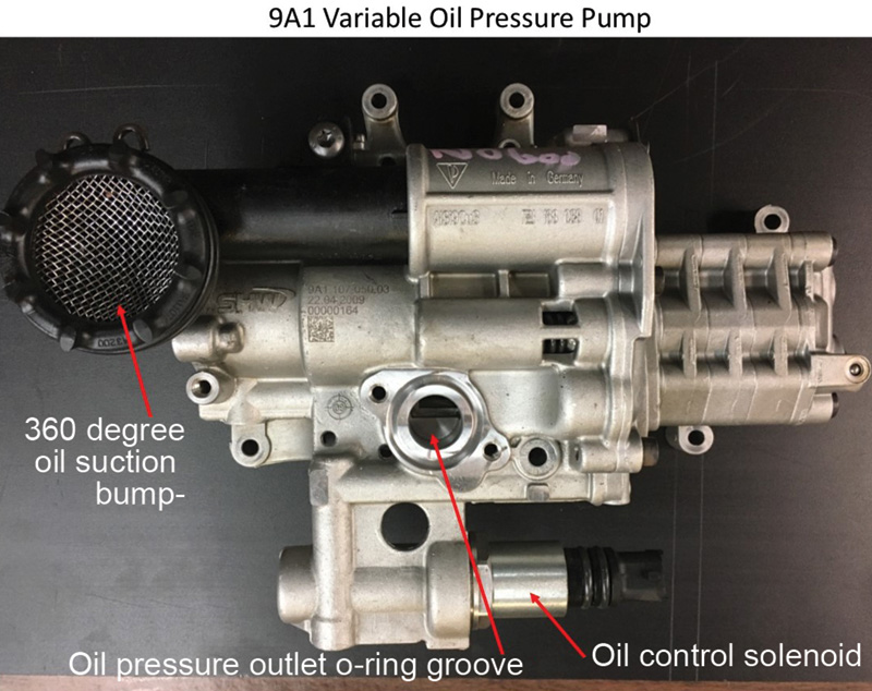
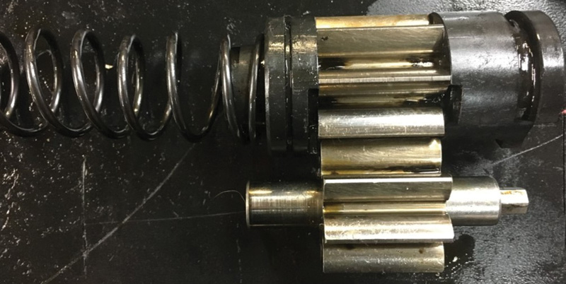
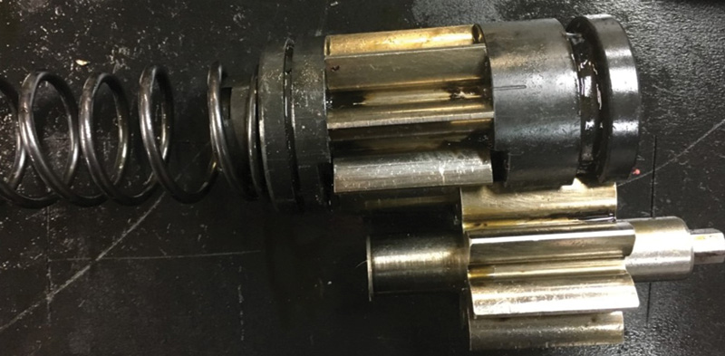
Take a look at Porsche’s solution with the variable oil pump. The pump is driven directly by the crankshaft via chain and sprockets. The drive ratio is 1:1 and one might conclude, and rightly so, that this would overspeed most gear-type oil pumps. You would be correct in assuming that but, enter the ECU.
With inputs from rpm, throttle position, manifold pressure, engine coolant and engine oil pressure sensors, the ECU is able to predict and then demand the proper pressure from the oil pump for the load. Again, no waste, no massive amount of bypassed oil returned to the sump. The engine therefore is not wasting power and fuel to make oil pressure and oil quantity that it does not need. The part number for this marvelous piece of technology is 9A1 107 050 03. The pump shown in the illustration is a variable displacement pump which uses an electronic solenoid to respond to the ECU’s commands.
A quick peek into the inner workings are shown in the photo with the gears in the maximum oil pressure position.Â
The drive gear in the foreground and the driven gear behind act as a conventional gear pump. The gears are in the full or maximum output position due to the force of the spring shown at the left. This is the engine start-up position and, as soon as the starter begins to spin the crankshaft, the ECU calculates pressure requirements. In almost all cases this position on startup is over demand, and if so, the ECU will command the oil pressure control solenoid (also pictured with updates) to apply oil pressure through internal passages to counteract the force of the spring and push the driven gear back, thus reducing the oil pressure which saves fuel and reduces emissions. See the photo which approximates a low oil demand position.
Over time, changes were made to the design of the pumps and attaching parts. All of the pumps still have pressure relief or bypass ports in the unlikely event of an over pressure situation.
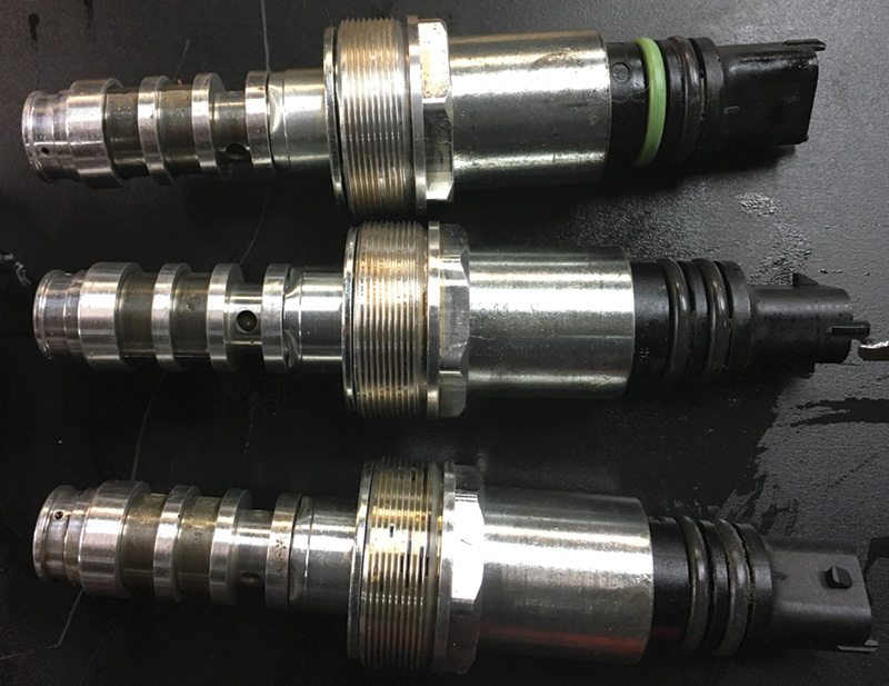
The first pumps by the SHW company (all manufactured in Germany for Porsche; part number 9A1 107 050 03 pump shown) was found to have some failures in 2009-2010 engines. The 9A1 107 050 03 pump was changed in March 2011 to a 9A1 107 050 04. Problems persisted with meeting the capacity demand so the oil control solenoid 997 606 203 01 was discontinued and updated in late 2011 to 997 606 203 02.
Up to this point these pumps, senders and controls were based on a 5 bar oil pressure scale. However when the oil was cold, or in colder climates, the oil pressure often went above the 5 bar limit.
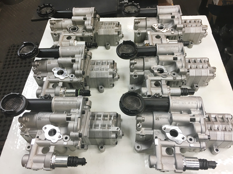
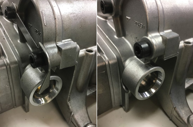
Also noteworthy, on close examination, the technician will find that the early pump designs utilized a full 360 degree skirt on the oil suction screen. A change was made to reduce the skirt to 270 degrees and raise the skirt up 10 mm above the inner surface of the lower oil pan.
Looking closely at the array of pumps, the keen eye may detect yet another anomaly with the suction screen. The 90 degree opening in the skirt faces the front of the engine on some of the pumps and rearward on others. We have not seen this mentioned in any workshop manual, but we are still looking. It is, for now, presumed that these engine are used for rear engine cars (991, Turbo,GT3) and the engine is turned around when used in mid-engine applications (Cayman, Boxster, GT4). However there is only one oil pump part number. We index the opening by rotating the skirt to face the crankshaft pulley on mid engine vehicles and toward the flywheel on rear engine applications.
Porsche then revised the entire system to a 10 bar scale. This is important to note when updating or backdating engines. The wire connector on the engine wire harness is different on the 10 bar wire harness. The tell-tale is that the plastic terminal connector at the oil pressure sender, above the oil filter, is a gray color in the early 5 bar engines, and the late model 10 bar changed to a black color connector. This is presumed necessary to ward off mixing and matching. When changing out a 2009 or 2010 engine for a 2012 and later new or used engine, be sure you re-flash the ECU with the latest file which is outlined in the factory service manual.
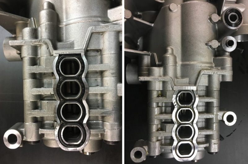
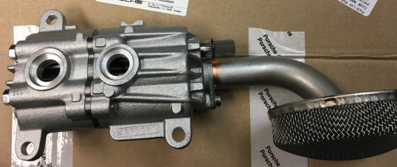
Several other noteworthy changes are visible on the exterior of the pumps. The early 5 bar pump has an o-ring groove on the pressure outlet flange. The inlet to the four scavenge pumps from the cylinder heads has a four compartment viton seal as seen in the side by side photo of the early and later pumps.
Both seals were eliminated in updated pumps. So the technician would be advised not to order these two seals as they are no longer needed. The 05 pump showed up shortly thereafter in March of 2014 and lasted until May of 2017 and was again updated to 9A1 107 050 11.
Another exterior change came when Porsche eliminated the steel locking collar that held the oil swirl pot manifold onto the pump.
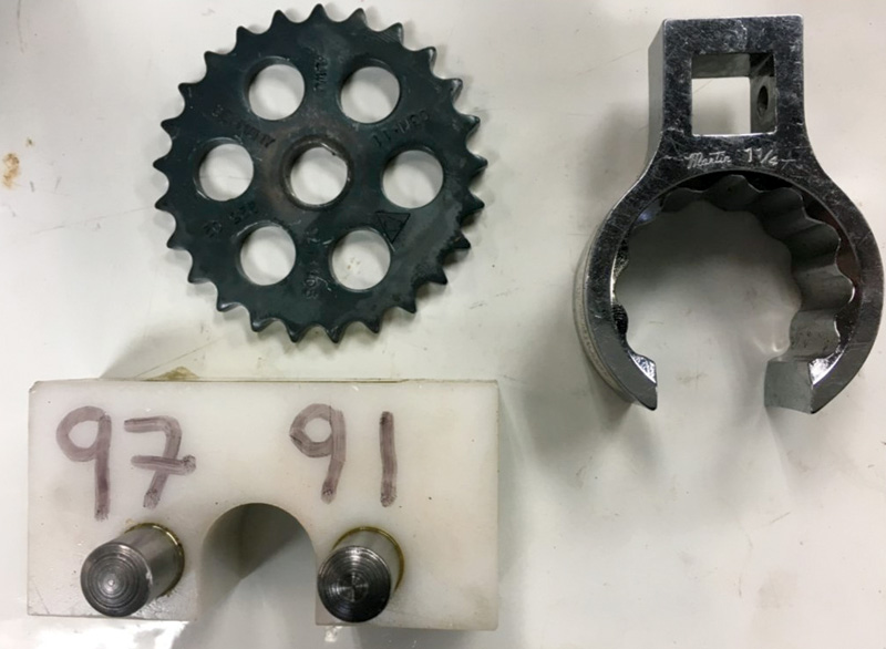
Whenever overhauling a MY 2009-2011 engine, use the newest update which at the time of this writing is PN 9A1 107 050 12, along with the 10 bar pressure sensor 948 606 213 00. Always replace the central locking screw that fastens the drive sprocket to the pump drive shaft , and watch the specified torque angle — it will surprise you for sure.
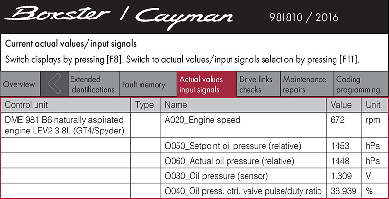
As far as shop diagnostics with no obvious fault codes, monitoring the oil pressure system on the dyno reveals some interesting and possible tell-tales for future failures.
Looking at the technician’s diagnostic screen, this vehicle is idling at 672 rpm, the ECU is calling for 1,455 hectopascals (hPa) of oil pressure (multiply 1,455 x .014537738 = 21.1 pounds per square inch) while the actual pressure supplied is within one pound. The oil pressure sensor is reading that pressure at 1.333 volts and is requesting a duty cycle of the oil pressure control regulator at 36.867 percent.
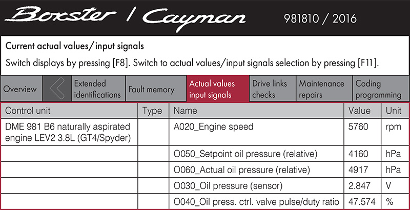
Run the car up on the rolling road (chassis dyno) and the tech can notice under heavy load at just under 6,000 rpm a deviation between the requested pressure of 4,160 hPa (60 psi) and the actual pressure of 71.5 psi with the regulator running at 47 percent duty cycle. We have seen this before with relatively cold oil. As the oil temperature reaches its 200 degree F temp, the requested and actual pressures are closer to each other. When the requested pressure is higher than the output pressure and the duty cycle is up, there could be cause to investigate. The ECU will flag the driver if the deviation opens up to what its algorithms calculate to be of potential failure.
Next installment, scavenge and vacuum pumps.
Download PDF


0 Comments