
You may think of them as ho-hum mechanical parts, but they still need attention, especially with wheel speed sensors.
There’s more to wheel bearings than meets the eye. Since even the earliest uses of the wheel, a means of reducing the friction where the moving hub meets the non-moving axle has been used, but we’ve come a long way since wooden bushings soaked in paraffin.
Modern cars have been using roller bearings almost as far back as anyone alive can remember, and the technology involved hasn’t changed much in a lifetime. But that doesn’t mean there’s nothing new under the sun.
Here, we’ll take a close look at wheel bearings, along with how they’re related to the wheel speed sensors used for modern ABS, traction management, and stability control.
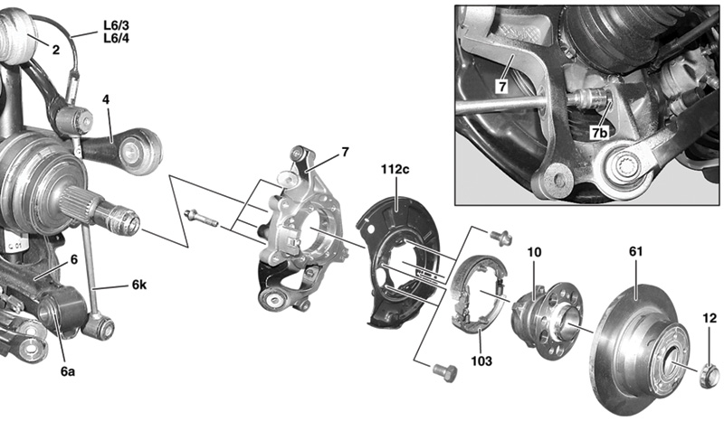
Let’s start with the easy stuff. Rear wheel bearings in rear-wheel drive cars have to support the drive axle shafts, so they’re always non-adjustable bearing assemblies. Some are pressed onto the end of the rear axle shaft, but more recently they’re bolted to the wheel carrier or hub in a holder.
The same goes for the front wheel bearings in front-wheel drive cars, as well as all four wheel bearings in 4MATIC models. In all these cases, replacing wheel bearings is a fairly simple operation: Take the old one off, install the new one. The details do vary from model to model, and in some cases the procedures needed to get at the bearings can be somewhat labor-intensive: When there’s an axle involved, it generally needs to be removed to access the bearings. But the bottom line in these situations is that the Mercedes-Benz Workshop Information System (WIS) will supply all the finer details of the procedures, because even though they don’t usually vary much, they do vary.
Mercedes-Benz requires wheel bearings to be replaced in pairs, meaning both left and right sides need to be replaced at the same time. Much like brake discs, you’d never replace just one, even if the other seems fine. This is also not a bad time to recommend brake discs and pads, even if there’s still some meat on the old ones, because there is virtually no extra labor involved. Naturally, we don’t want to cheat our customers, but in our shop if the pads and/or discs have less than about 10K miles left on them, we’ll explain the situation to the customer – including our estimate on how much pad and rotor life remains – and ask if they want to replace them anyway, since they really only have to cover the parts cost. Some of our customers consistently decline, but most of them are happy that we can save them some money by doing this.
We also take the time to check all the steering and suspension parts. Wheel bearings are not likely to fail on newer cars, so by the time this job is needed the vehicle has seen quite a few miles. Checking everything out carefully takes only about 15 minutes, and we always write on the work order what we did and what we found. Most of the cars we get are regulars, so we’ve been keeping an eye on things over the years, but we find that our customers keep coming back because they can see we’re looking out for them and their cars.
Then we come to the front wheel bearings that need adjustment. While most technicians working for even just a few years have done this job before, let’s walk through it carefully, closely following the WIS work instructions. Taking the E-Class as an example, this basic procedure has remained unchanged from before the 123 model to at least the 212 model. Really new cars, like to 213 and 205 C-Class, are different, but we’ll get to that in just a moment.
The theory of wheel bearing adjustment is that a constant pressure on the bearing rollers allows for a more consistent lifespan. Too little pressure, a result of too much bearing clearance, and the wheel can “rattle†the bearings. This allows shock forces on the bearing rollers and races to actually put microscopic dents into the bearing system. Roll over the tiny imperfection often enough, and the bearing will fail. Likewise, too much pressure from too little clearance and the excessive compression forces cause the bearing to overheat, and hot metal doesn’t have the durability of cool metal. In other words, faulty adjustment is bad for the bearing.
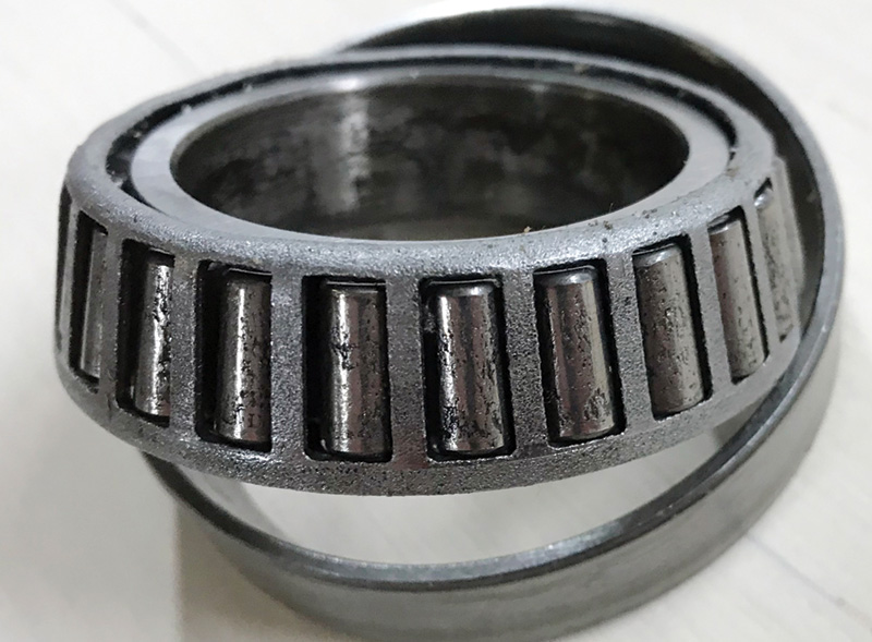
Bearings of all types have distinct ways of failing. While a mechanical engineer can explain and even predict these failures using advanced math, let’s just get at the basics. Even a correctly installed, clean, well-lubricated, and properly-loaded bearing will fail by fatigue, from the stresses of repeated contact. Just like bending a coat hanger wire enough times eventually causes it to break, compressing the surface of the bearing races and rollers (or balls, needles, whatever) bends the metal at the surface just a tiny bit, and after very large number of cycles, the molecular bonds start to break, just like that coat hanger. This causes very thin flakes of the surface metal to break free, contaminating the bearing and leaving rough spots behind. Once this failure mode, known as “spalling,†begins, the process accelerates due to the small metal particles now added to the contact points, similar to how beach sand might affect a bearing. This, by the way, is the normal failure mode when bearings “wear out.â€
A typical wheel might rotate 600 times per mile, so each point on the race of a bearing with (for example) 25 rollers will see 25X600 = 15,000 compression/decompression cycles pressing on it each mile. So when that E320 comes in with 100K on the clock and doesn’t have a noisy front bearing complaint (hardly any do at that mileage), we express amazement at the fact that those bearings have experienced over 1.5 billion bending cycles and are still going strong.
Ah, but sometimes they don’t last that long. There are a few causes for early bearing failure, but they almost always come down to one of two things: heat or shock. Heat comes from the excess friction caused by a too-tight bearing, contamination, lack of lubrication, or an outside influence (think acetylene torch). Shock comes from excessive bearing clearance, an accident, or a careless technician with a hammer.
Here’s the procedure that works for just about every Mercedes-Benz model we’ve ever seen (but as always, WIS has the details):
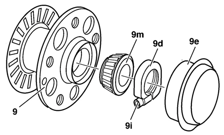
We start by removing the front wheels, brake calipers and discs. If you have a SBC-equipped model, be sure to deactivate the system first. Using our trusty hub cap remover, the center cap comes off. Resist the urge to pry it out with a chisel or screwdriver – bending one (even a little) will ruin it, and grease will eventually leak out onto your customer’s shiny alloy wheels.
With a hex wrench, loosen the clamping screw on the axle nut and unscrew the nut from the spindle. In some models, there’s a bronze spring and contact at the end of the spindle. Be sure to save this for re-use, unless you bought a new set. Shake the hub a little to pop out the covering washer and outer bearing, and remove them. This is a good time to note the condition of the wheel bearing grease: Is it still green, as original, or is it black? Does it contain “glitter†(the tiny flakes from a failed bearing) in it? Be sure to save some for the customer’s inspection.
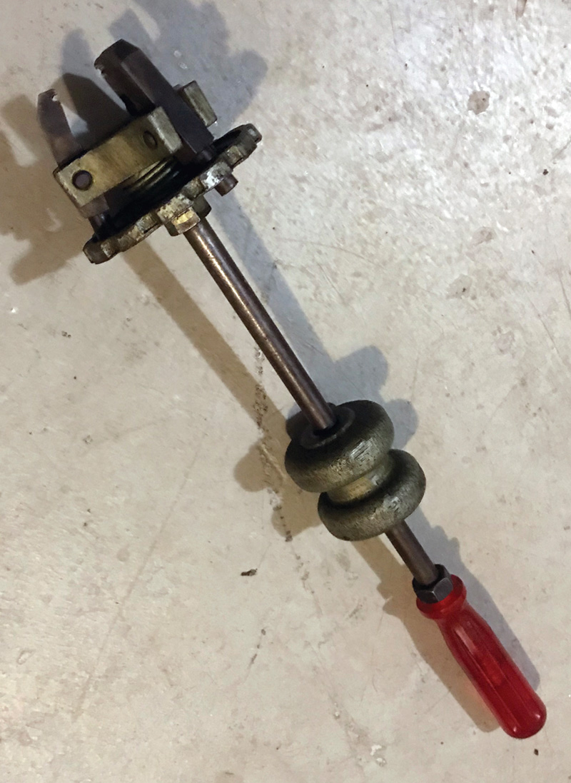
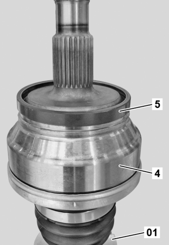
Pull the hub straight out off the spindle, and bring it to the press. If the hub is stuck, there’s a slide-hammer-type puller that will pop it right off. In older models – late 1990s and earlier – the speed sensor tone wheel (also known as a pulse wheel or generator) is a series of grooves or splines machined into the hub. In later models, the tone wheel is a separate slotted disc at the back of the hub, while in still newer models it is part of either the inner seal or bearing assembly. No matter the technology, take pains to avoid damaging it unless it’s being replaced. Note that in some models have you remove the speed sensor to avoid damage.
Using the seal removal tool or a brass drift, pop out the inner seal, pull out the inner bearing, and use the bearing race tool to drive out both outer races of the outer and inner bearings. Clean and carefully inspect the hub, and if anything is damaged, replace it.
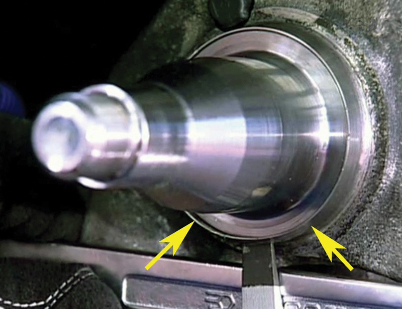
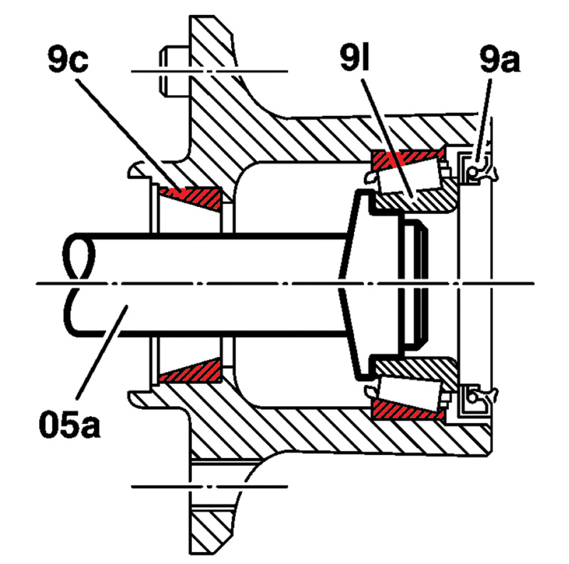
On the spindle, of particular importance is the surface that the inner seal rides upon, which needs to be smooth and shiny. Also inspect the spindle bearing surfaces, and if discolored from heat it also needs to be replaced. In some models, a thin metal seal carrier from the old seal might remain on the spindle. Check for it carefully and, if found, pry it off before installing a new seal with carrier. In the accompanying photo, an arrow points to the metal carrier. Then start reassembling.
First, install the inner races of the inside and outside bearings using the installation tool. Then pack both bearing cages full of the Mercedes-Benz green high-temperature bearing grease (A002 989 00 51). Remember, everything has to be super clean, since even a small amount of debris will cause premature failure. Install the inner bearing and then the inner seal, and pack the specified amount of grease into the hub. For a 204 model, for example, 60 grams (just under half a tube) gets placed inside the hub in the space between the inner and outer bearings. Lightly grease the spindle and the inner seal lip, and gently install the hub onto the spindle. Be sure to avoid cocking the spindle off-axis even a little, otherwise the seal can be damaged. Push the outer bearing onto the spindle and into the hub, then install the spacer washer and spindle nut. Hand-tighten it.
While continuously spinning the hub, tighten the spindle nut with a wrench tightly, until the hub starts getting noticeably more difficult to turn. This sets the bearings and makes sure the races are installed flat. Loosen the nut and re-tighten it barely finger tight. Lightly grease the hub faces that will contact the brake disc — just a little to prevent seizing later on.
At this point, all the greasy parts are done, so we take a few minutes to clean up, change gloves, and check everything. Install the brake disc, remembering that the brake disc safety screw is a single-use fastener. Always replace it after it has been loosened. Tighten the new safety screw to spec (usually 9 Nm).
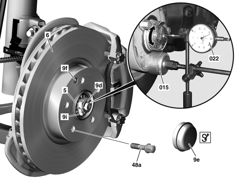
Now comes the tricky part: the actual adjustment. Keep the brake disc from wobbling by fastening it to the hub. Use a wheel bolt, opposite the safety bolt, to hold both sides of the disc tightly to the hub. Attach the magnetic base of a dial indicator to the brake disc, with the indicator tip on the spindle nose – see the image. Push and pull the brake disc/hub assembly in and out with a fair amount of force, but absolutely in line with the spindle, and measure the free play. Specification is 0.01 to 0.02 mm (0.0004 to 0.0008 in.) of free play. Tighten or loosen the spindle nut in very small increments until the spec is reached.
In a practical sense, we find it easiest to loosen the nut until Iwe can actually feel some play. The hub/disc assembly makes a kind of clicking sound when pushed and pulled. Check the adjustment – probably quite a bit loose – and very slowly tighten the spindle nut, maybe a 20th of a turn at a time. This might take a few tries to get just right, and experienced hands can feel the right point. There is definite and audible movement (it might take a quiet shop), but not much. Once you have it right, tighten the hex locking screw to 11 Nm, and re-check the adjustment. Repeat until it’s right.
When pushing and pulling, don’t use so much force that you move the steering or have the brake disc moving relative to the hub. The best we can describe the force is about as much as it takes to push a flat brick across unpainted concrete.
After the clearance is adjusted, put 15 grams of grease into the hub cap, and, using the slide hammer to avoid damage, pop it back on. When the wheel hub gets up to temperature, the grease is partly liquefied and will flow out of the tiniest gap on the wheel hub cap, staining your customer’s wheels. If in doubt as to its condition, replace it.
For newer models like the 205 C-Class and 213 E-Class, the bearing is an assembly that bolts onto the wheel carrier, no adjustments needed. Four bolts, tightened quite a lot (see WIS for the specs), hold the bearing and carrier in place. Kind of an anticlimactic letdown after all that work on the earlier models.
Then, there are the tone or pulse wheels. In early ABS vehicles, there were three: one on each front wheel, and a third at the rear differential. The analog sensors of the era detected the “splines†machined into the hub or on a special wheel attached to the pinion shaft at the differential. The introduction of ASR required each wheel to have its own sensor, so in the rear the machined hub design was used. Sometimes, these splines got dirty and caused problems. A wire brush and a careful inspection was the usual cure.
Not long after, active digital sensors were introduced, which use the Hall-effect to sense magnetic pole “lines†invisibly embedded into an object. At the rear axle, a magnetic tone ring is pressed onto the axle shaft. Taking the old ring off can be done with a drift and hammer, but the new one must be pressed onto the axle. Hammering it even a little can crack or demagnetize it.
In the front, at first the machined splines gave way to a slotted disc. Then, a magnetic pattern was embedded into the inner seal, or in later cars with non-adjustable bearings, the rubberized edge seal of the bearing itself. With these magnetized components, it’s important that you don’t accidently demagnetize them. Using a magnet near them (duh!), or striking them will cause damage, as can strong vibrations such as from a near-by hammer blow.
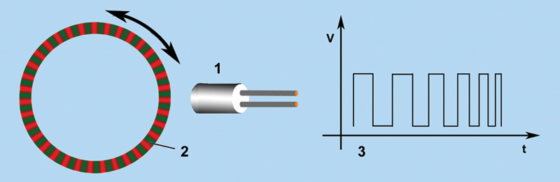
An important implication of these magnetized tone wheels is that if the traction control system is acting strangely, or there’s a DTC related to wheel speed or wheel speed sensors, remember that the cause can include the tone wheel. Your best bet is to use an oscilloscope to monitor the speed sensor’s signal output, ideally using the Mercedes-Benz breakout box and correct test cable. The Hall-effect sensors need power and ground to function, and remember that they switch on and off to produce pulses that are grounded. So, measuring from output signal to ground won’t give you a reading. You have to measure from output signal to power! Spin the wheel at about one revolution per second and look for missing, too-long or too-short pulses, which are indications of tone wheel troubles.


0 Comments