
Battery, grounds, security, or…?

Everyone has encountered this complaint on a work order that reads something like this: “Customer states vehicle does not start, will not crank.†There was a time when this entailed a fairly simple diagnosis and repair — nine times out of 10 simply a battery issue — but now with anti-theft packages and complicated wiring schemes there’s more here to diagnose than meets the eye.
While there are indeed multiple complicated possible faults that may cause your customer’s distress, it’s best practice to not jump to the most difficult diagnoses, but start simple.
Strategy-Based Diagnostics
Most of you with some experience and training under your belt are aware of this term. This is the process whereby a good technician knows how to combine experience, service information in terms of manufacturer’s specifications, scan data and test results, as well as their own individual test results to arrive at a theory of what’s wrong with the vehicle. At that point, you use established techniques and equipment to prove your theory, then you make the repair.
Most authorities will agree that the first step in any diagnostic procedure is to verify the customer’s concern. You’ve all had this happen: You’re brought a no crank/ no start, you put the key in the ignition or hit the start button, and, bam, the car starts right up. This is a perfect opportunity for your service adviser to communicate with the customer about what’s going on with the car. Is this the first time this has happened? Most likely you’re dealing with an intermittent fault. Gathering as much information as possible from your customer will give you more ammunition to shoot at the problem. Let’s assume now, however, that you verify the customer concern and the vehicle indeed has a no crank condition.
Differential Diagnostics
Differential diagnostics is the process of differentiating between among multiple conditions that exhibit similar symptoms, which is common practice in the medical profession. You compile a list of possible causes of the symptoms, then perform observations and tests to rule each possibility in or out. Let’s make a list of possible causes for this case:
- Battery
- Fuses
- Starter
- Wiring
- Security/anti-theft
- Control modules and relays
Voltage
All cars need sufficient voltage to crank, of course, but also enough amperage delivered to the right places to facilitate the operation. We don’t even plug in a scan tool if the initial voltage is below 12.6, or we get a huge drop in voltage under load. You may get many under-voltage or false codes, so it’s best to address the battery first before performing a scan.
Batteries
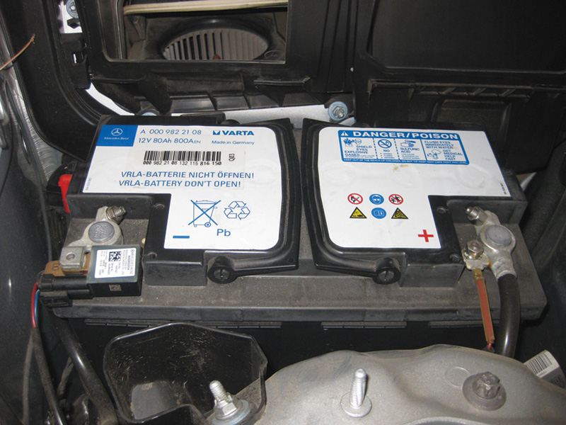
A Mercedes-Benz battery may be either AGM (Absorbed Glass Mat) or traditional lead acid. It may also be located in various places depending on the model. Some are in the trunk, some are under the hood, and some are under the seats. Also, some models have two batteries for different purposes. One is the starting battery, and the other is the auxiliary battery. You will want to check them both using a high-quality battery tester.
NOTE: If it is deemed necessary to charge the on-board accessory electrical system battery (G1/7), then the starter battery must also be charged.
On vehicles with more than one battery, the ground leads should be disconnected from the others while one is being charged or tested. Check the battery voltage of the on-board electrical system battery via the instrument cluster or a multimeter, as described in the WIS document AR54.10-P-1132A. A battery should be charged when the measured voltage drops below 12.2 V. A good tester will tell you if the battery needs to be charged and retested. Some testers have a mode of diagnostic charge. This mode charges and tests the battery at the same time to give a very accurate analysis of its condition. If the vehicle has been inactive for six months or longer, the batteries must be charged prior to putting the vehicle back into service to counteract any self-discharge.
NOTE: The instrument cluster displays a white battery symbol with the text, “Visit Workshop,†if the auxiliary/additional battery voltage is < 11.5V. If the auxiliary/additional battery is between 6.0 V and 11.5V, it will be charged by the front SAM (N10/1) at a rate of 150 mA when the engine is running, or STAR Diagnosis is left connected and set to charge the auxiliary battery. If the measured voltage of the auxiliary/additional battery is below 6.0V, it should be replaced.
Upon finding a faulty battery, replace it and verify the repair. It’s important in some models to register the battery. After you have indeed solved the problem by replacing the battery, be sure to conduct a full system scan to be sure there are no underlying issues concerning the no start. Why did the battery fail? Just due to age, or is there perhaps a draw on the system? Is the charging system operating properly? Let’s move on with the assumption that the battery tests “good†and has been eliminated as a cause.
Fuses
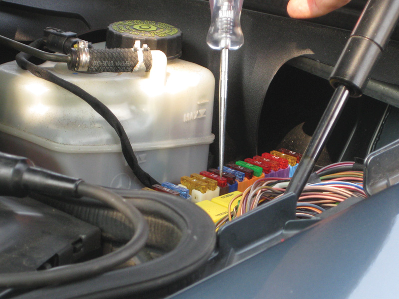
This seems so simple, but in complex modern vehicles this step is often overlooked. Before moving on to scanning the vehicle, you should check all the vehicle’s fuses. Sometimes there will be three or more different fuse blocks, and you might be tempted to check only those that seem related to starting the vehicle. But experience has taught us that fuse descriptions can be misunderstood. You will be quite frustrated to find out that the cause of your concern was simply a fuse that you thought was unrelated.
Quick Test
Perform a quick test on the vehicle and record, diagnose, and erase codes. Many unrelated codes may pop up due to the no-crank condition, but try only to pay attention to those related to the symptom at this time. Many non-factory scan tools will not communicate with car if the message from the Electronic Ignition Switch for “Key On†is not working.
If the key turns in the ignition switch, but no warning lights come on in the instrument cluster, try to turn on hazard or dome lights to allow scan tool communication and check for fault memory in the Electronic Ignition Switch (EIS). Continue when a fault code is set for Electronic Steering Lock (ESL). Even if you have some anti-theft or ESL codes, it would still be prudent to verify the signals at the starter itself before going into more complicated EIS issues.
Starter Issues
As mentioned, the starter needs the proper voltage delivered at the right amperage in order to crank the engine over. A voltage drop test to the main connections and the signal wire to the solenoid are in order next.
Looking at our symptoms, check the signal wire first. Consult the wiring diagram if needed, but this should be the smaller wire at the starter solenoid connection. Check for a good signal when trying to crank the vehicle. If you have a good signal (>10.5V), connect your multimeter in parallel with the positive battery terminal and the heavy positive lead of the starter connection. In the DC volts mode, you should have no more than .2V per connection voltage drop when the circuit is loaded. In other words, turn the key to the crank position or hit the starter button. Do the same with the ground side of the circuit. Typically, .6V is the most you want to see for a voltage drop. If it is greater, proceed with checking and cleaning connections. If the starter has a good solenoid signal, and the main cables are sound as revealed by your voltage drop test, you can now deduce that the starter itself is faulty. One step that can be helpful at this stage is to give the starter a tap with a small hammer while a helper turns the key to the start position. If the engine now cranks, the starter has an armature issue and it’s time to replace it.
Complete the Vehicle Test
Having eliminated the battery, fuses, starter wiring and starter, now you can address possible EIS faults. With the symptom: “No crank/no start/ESL and IC do not respond to key input,†you should refer to topic number LI80.57-P-051521 for some troubleshooting tips.
Here’s the procedure outlined in this particular tip, which is quite common, starting with the complaint:
- No crank/no start/intermittent no crank.
- Communication via SDS to Electronic Ignition Switch N73 (EIS/EZS), and or short test may or may not be possible at time of fault.
- Scenario:
- When accessing the passenger compartment, the message center in the ICM will illuminate (eventually the message center will time out and shut down, and will not illuminate until the CAN is activated via the interior lock/unlock switch).
- The key will turn in EIS N73.
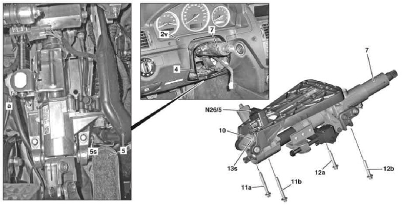
- The ESL N26/5 does not activate/respond (or the steering wheel remains unlocked at all times).
- The warning icons in the ICM will not illuminate.
Cause:
Internal issue with the Electronic Steering Lock N26/5 (part number A 204 545 57 32)
Remedy:
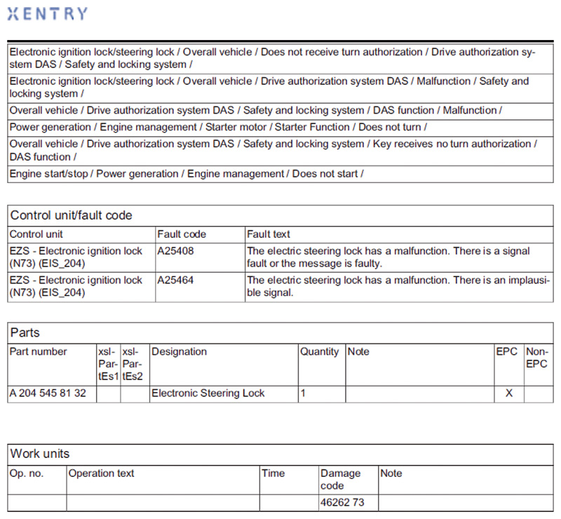
First, perform a complete guided test of the drive authorization system, and transmitter key via the “Tests†menu in the EZS control unit. Fault codes A25408 and A25464 in the Electronic Ignition Lock N73 (EIS/EZS) direct you to replace the Electronic Steering Lock N26/5.
NOTE: If no fault codes are stored, do not replace any parts!
Check the part number on the Electronic Steering Lock N26/5. If it is A204 545 57 32, please replace with part number A 204 545 81 32 using WIS instructions AR46.10-P-0910CW.
NOTE: It is possible to corrupt the Electronic Ignition Switch N73 if it is replaced prior to replacement of the suspect ESL. Also, insure that the CAN does not time out before the programming of the ESL with the workshop key is completed. If replacing both units, make sure to plug in the new ESL first.
Replacement of the ESL will require a programming workshop key to perform initial startup. After replacement of the ESL, insert the workshop key into the Electronic Ignition Switch (EIS). Once the light in the workshop key turns off, remove the workshop key and insert the ignition key. After a couple of seconds, you will be able to turn the ignition key, allowing the car to start. Replacement of the Electronic Ignition Switch (EIS) is the same, but you will need to program the VIN into the Electronic Ignition Switch (EIS) with scan tool functions. Be aware that these parts are on the Mercedes-Benz Theft-Relevant Parts (TRP) list. See the factory website for further details.
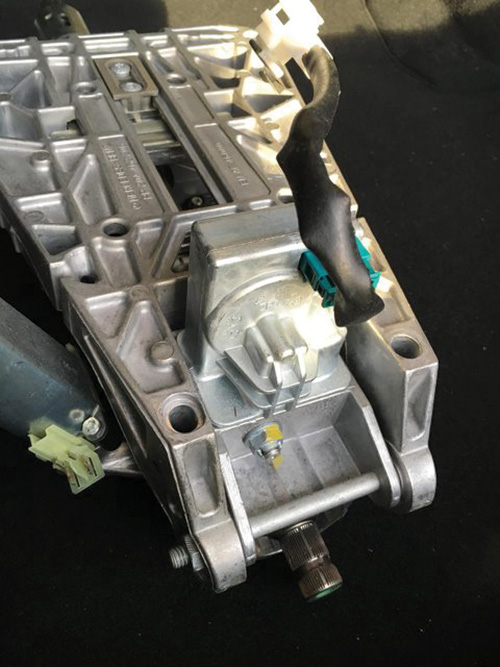
Function and Task of ESL and EIS
The electric steering lock control unit, located on the steering column, processes information from the electronic ignition switch control unit (N73) and is connected to it by a bi-directional serial data line. After the unlocking operation, the power to the locking component is switched off to avoid unintentional locking.
The following is the scope of the ESL:
- Calculation of Hash value
- If the Hash value is incorrect and the unlocking position is not reached or not recognized, an error message is transmitted to the electronic ignition switch control unit.
- Position monitoring of locking bolt via two hall sensors
- Switching on integrated motor via alternating relay for locking and unlocking bolt
- Locking steering column with locking bolt
- Inputs:
- Circuit 30
- Circuit 31
- Serial data line to electronic ignition lock control unit
Output:
- Serial data line to electronic ignition switch
- control unit
The electronic ignition switch control unit is located on the right next to the steering column (204 models).
The EIS is the master control unit for the following functions:
- Drive authorization stage 3 (DAS3)
- Central locking (CL[ZV])
Scope of tasks for EIS:
- Communication with transmitter key when transmitter key (A8/1) is inserted, via infrared signals and inductive energy transmission.
- Encrypted data exchange according to Hash method for key identification with transmitter key
- Transmitting hash code
- Rotary-angle-dependent activation of circuit 15R, circuit 15 and circuit 50 after identification of transmitter key
- Mechanically locking transmitter key in turned positon and mechanical rest between start and drive position
- Mechanical reception and read-in of KEYLESS GO start/stop button (S2/3) via additional contact switch in EIS
Inputs:
- Circuit 30
- Circuit 31
Outputs:
- Circuit 30 to ESL
- Serial data line to ESL
It should be noted that the EIS and ESL are participants of the interior CAN and chassis CAN, and are not a gateway.
Drive Authorization System – DAS
The drive authorization system is a combination of the EIS, ESL, ME-SFI, and electronic transmission control units all communicating together to start the vehicle.
The encrypted data is exchanged between the transmitter key and the EIS via an infrared signal. The code is then computed in dialog between the key and EIS using the above-mentioned Hash method. The corresponding value of the key is transmitted to the other control units by the EIS. Check, release, and feedback are performed separately by each control unit.
When the transmitter key is inserted in the EIS, it is inductively supplied with power so that even when the key’s battery is dead the vehicle can still be started. You will, however, have a message in the cluster display if the key battery is dead. Asking your customer if he or she has another key is always a wise part of the diagnostic platform in the event that the first key is defective.
As you can see, we’ve gone from simple to complex. Using proven methods, diagnostic strategies, and proper equipment, you should be able to diagnose even the most difficult no-crank concerns.
Download PDF 〉


0 Comments