
2.0L TFSI Automatic Transmission AWD
Part 1 Introduction – Thermostat Coupling
The article was created because of a personal intervention with this vehicle because of a few factors. One of the issues was a “thermostat outlet†leak that unexpectedly developed and required immediate attention. Finding the replacement part, o-rings, and replacement bolts was a task all onto itself.
Part 2 Introduction – Heater core service
Many months later, the heater core developed another issue where the driver’s side maintained normal temperature and the passenger’s side was experiencing far cooler temperatures at any rpm or road speed. Again the problems started when trying to acquire the correct parts, and this time devised a plan to clean the core, rather than replace the heat exchanger and related o-rings and clamps. Let’s see how this works out.
As previously mentioned and repeated in past articles, make sure a clean and stable power supply is attached to the vehicle battery, scan the entire vehicle, BUT at least apply basic settings to the HVAC system to ensure no control module or blend door motor faults exist. If any parts are to be replaced, ensure the service literature is ready and document the procedures.
Similar to others and the VW suggestion
VW shares similar interior heating systems with many models of this generation. This type of system can also be found with some Audi models as well. The choice this time was to not follow the VW recommendations to:
- Drain the coolant and flush with water (what drains?).
- Add 4 liters of vinegar and top off with water.
- Run the vehicle at high rpm (2,000 to 2,500) (who’s going to hold it?).
- Drain the solution, flush and refill with G13 (replacement for G12).
- Test again and consume more time.
Out of the box
The requirement was a) disable/block the cooling lines; b) attach a pump with accessories and let it work on its own, and; c) not follow convention.
Part 1 Solution – Thermostat coupling
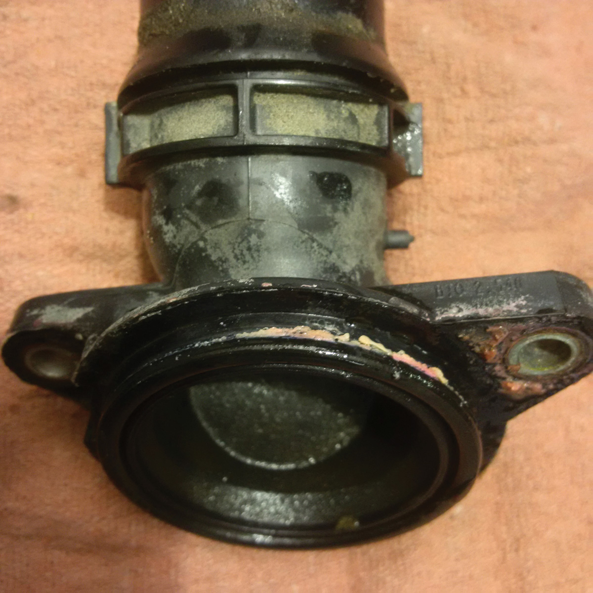
Fortunately a very good OEM parts staff member was able to send images of the required parts. Clear information is paramount to repairing and replacing this poor design. The new replacement is by far a better design and reasonable toward keeping that leak at bay.
This version is one style that will certainly leak over time especially during expansion and contracting of the assembly(s). Make sure the mounting bolts are replaced and all other plumbing is secured correctly during assembly.
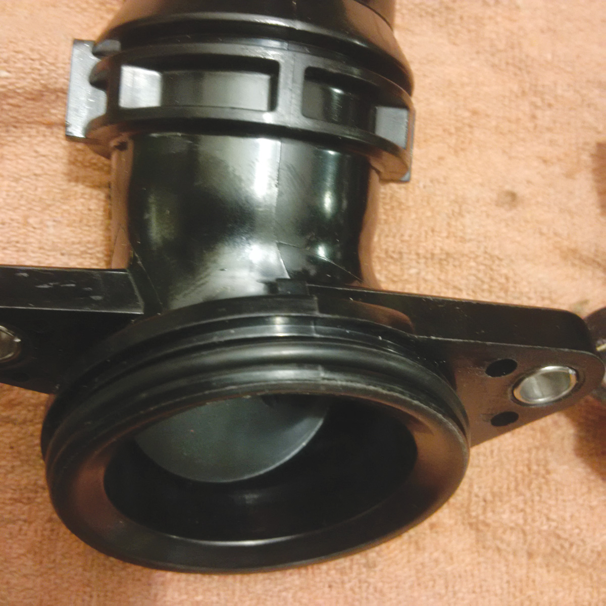
This new style of coupling is a marked improvement to keep the o-ring in place during the expansion and contraction of the engine and plastic assemblies. The key to this is also finding the correct o-ring at the radiator hose coupling. It MUST be replaced or expect a leak in the near future.
For the moment, this new version is still holding up well after a year of service with combined city and highway driving.
Part 2 Solution – Heater core service
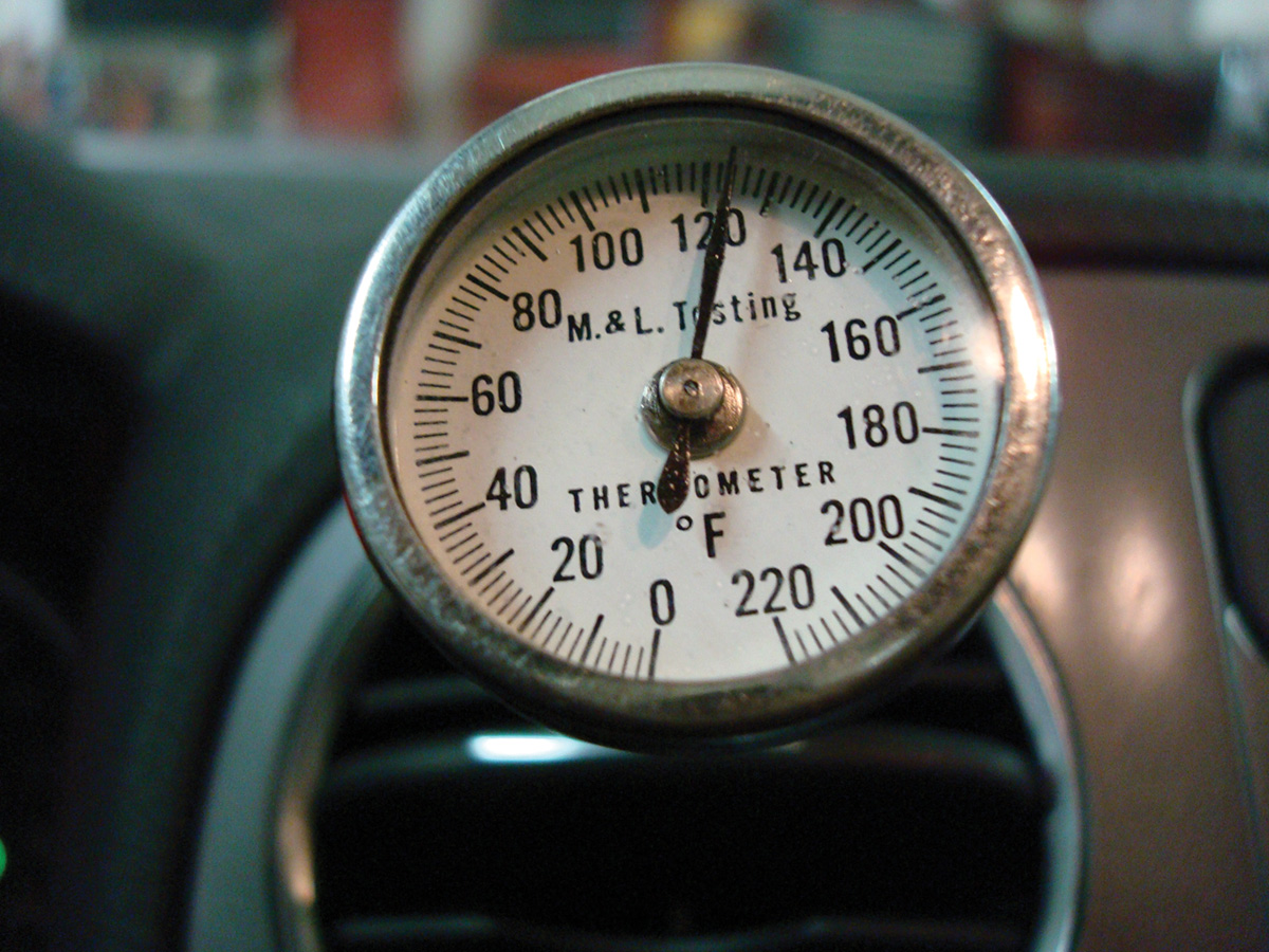
The driver (my kid) complained during one of his trips and experienced a very cold interior on the right side. With a scan, adaptation/basic settings completed with the HVAC controller, we did reproduce the difference in temperature at the outlets. The difference was quite remarkable with the driver’s side indicating 120 degrees F and the passenger’s side indicating 70 degrees F.
The correct method (cold weather test) to measure temperature is while driving the vehicle. The in shop method will not indicate the correct temperature because the entire heating box will warm because of convection. The road test tells a far superior story with these models.
The conversations with smart technicians indicated a problem with the interaction of the coolant (G12) and the manufacturing process of the heater core. With some help and sourcing spare couplers, the plan is set to “flush out the core†with CLR that is heated in a pail.
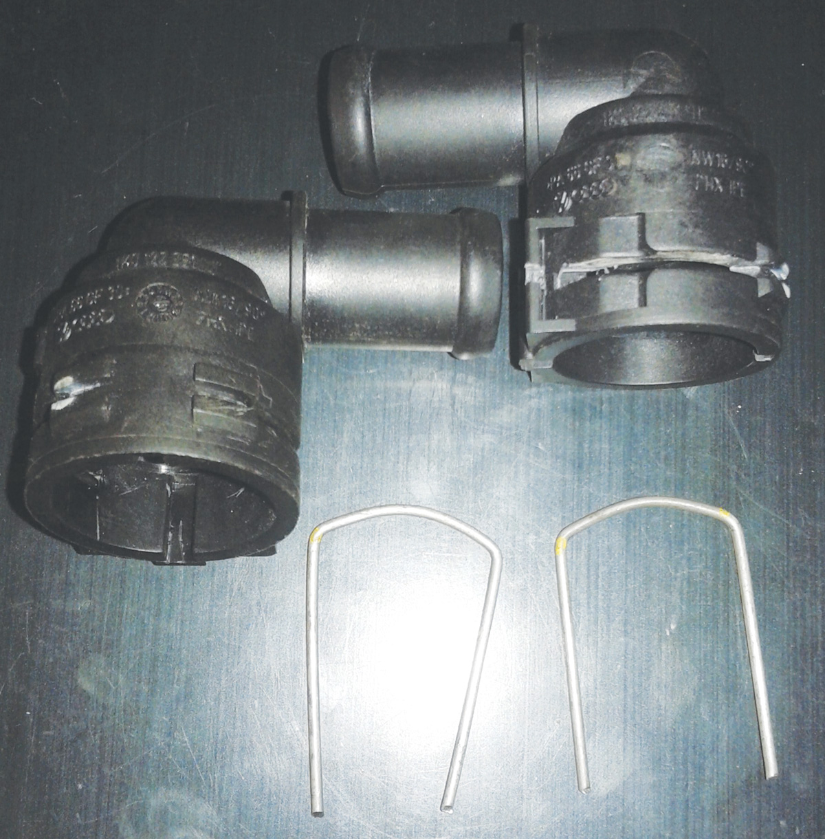
The test and idea was to push fluid with a 12V water pump (reversing flow occasionally) and maintaining the flow for about 3 hours. This was decided because there was little “babysitting†and whatever was captured in the return screen should help indicate what was restricting the coolant flow within the core. The test is personal time and mostly experimental. I was rather proud of the design with hand made retaining clips.
The VW coupler part numbers: 1K0 122 291 “J†and 1K0 122 291 “H.â€
Measuring the couplers and adding some clear hose with brass connections offers a view of force feeding the heated fluid. The brass couplings were attached using quality garden style or washing machine hoses.
The threaded garden hose brass couplings kept everything simple to swap the lines over for a reverse flush. Note again that the fluid is heated. The heater is arranged so that it is insulated from the plastic pail and secured from the pump. The heating element does get HOT and MUST be immersed in the fluid. The element MUST not glow (increase the fluid level).
Note:
- The shop MUST be well ventilated when warming the CLR.
- Always monitor the fluid level and temperature.
- Avoid spillage and leaks when using CLR.
- Use face and hand protection at all times.
- Make sure all electrical connections are tight and safe.
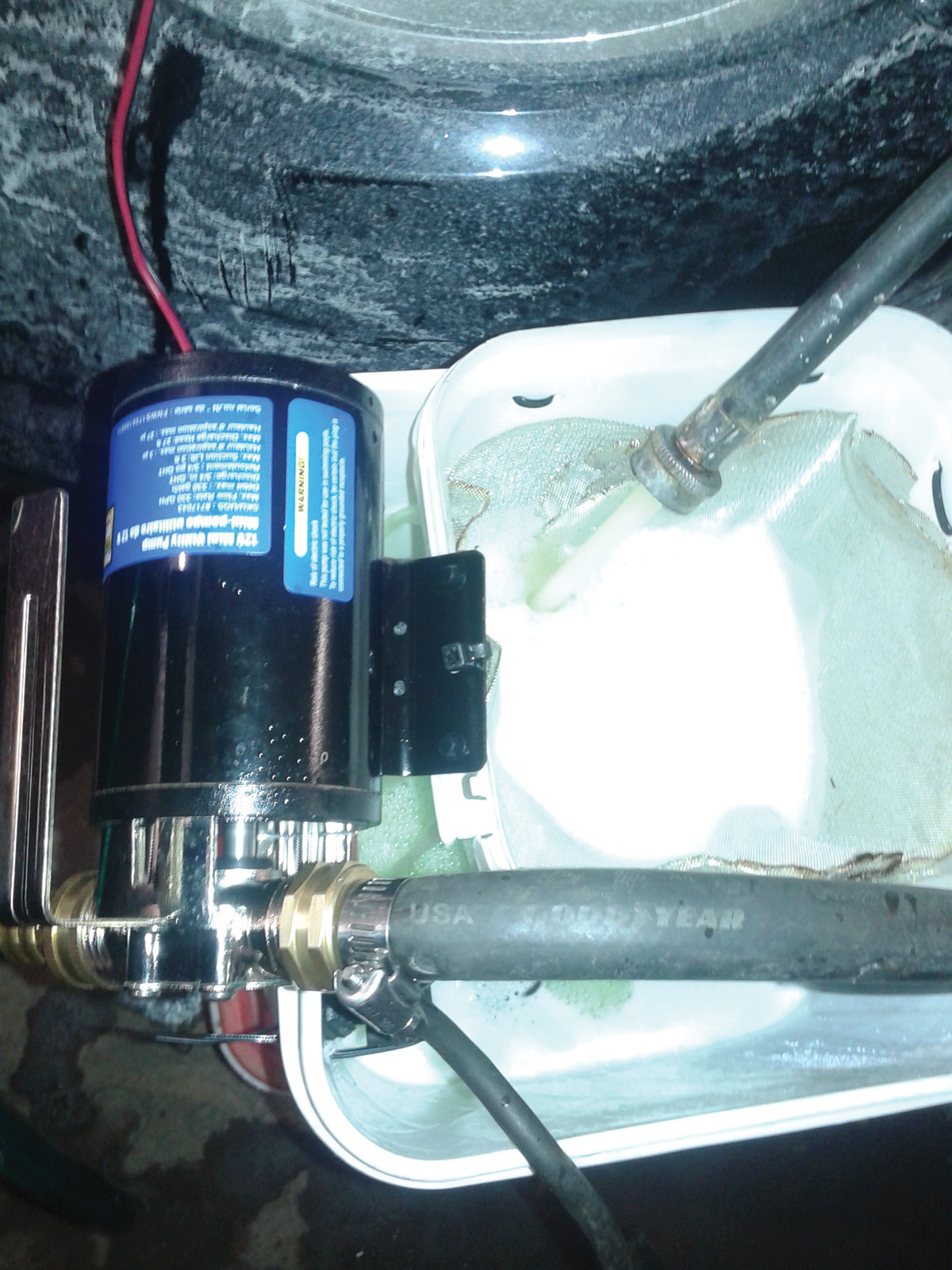
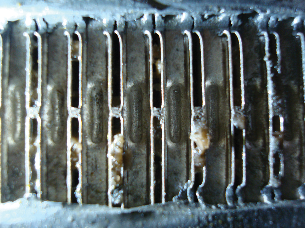
The pump and flow design allows heated fluid to be pushed into the core and returned fluid filtered into the meshed screen for inspection. With some time, the next image shows what was ejected from the core about an hour into the flush procedure. Reverse flushing the chemical solution also produced more contaminants over the course of three hours.
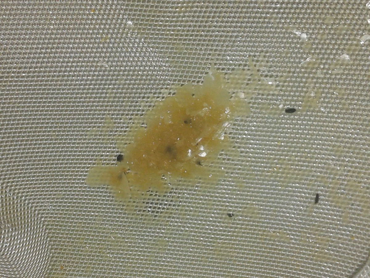
With time, this particulate matter did build and felt more like a slime and with enough heat and fluid, would spread on the meshed filter.
After this entire episode and with the Tiguan reassembled, the temperatures seemed to be hotter in the service bay. Bleeding the cooling system is simple when the smaller diameter upper hose purges into the coolant reservoir.
Now for the road test at different speed ranges and we must admit this episode was a dramatic failure!
Not much really changed and, if anything, this increased the outlet temperature by only a few degrees at the passenger side during an evening drive.
If anything was learned, the flushing tool may work only to maintain a core that doesn’t react harshly to G12 or maintaining/cleaning heater cores every other year for other models. Future maintenance?
Part 2 Solution – Heater core replacement
This is what was learned about CLR. The formula was changed to a lactic acid to facilitate the chemistry as eco friendly and I am a firm believer of handling the planet with kid gloves. There has been come chatter about ZEP at the local Home Depot. This solution is a calcium, lime, and rust remover and is potent. Follow the directions for all products. Again, if this is part of service, keep the filtered solution(s) for re-use and store safely.
From the beginning
Start with a cool engine, reservoir cap removed and clip the heater hoses. The next image indicates one screw to be removed. Don’t lose it!
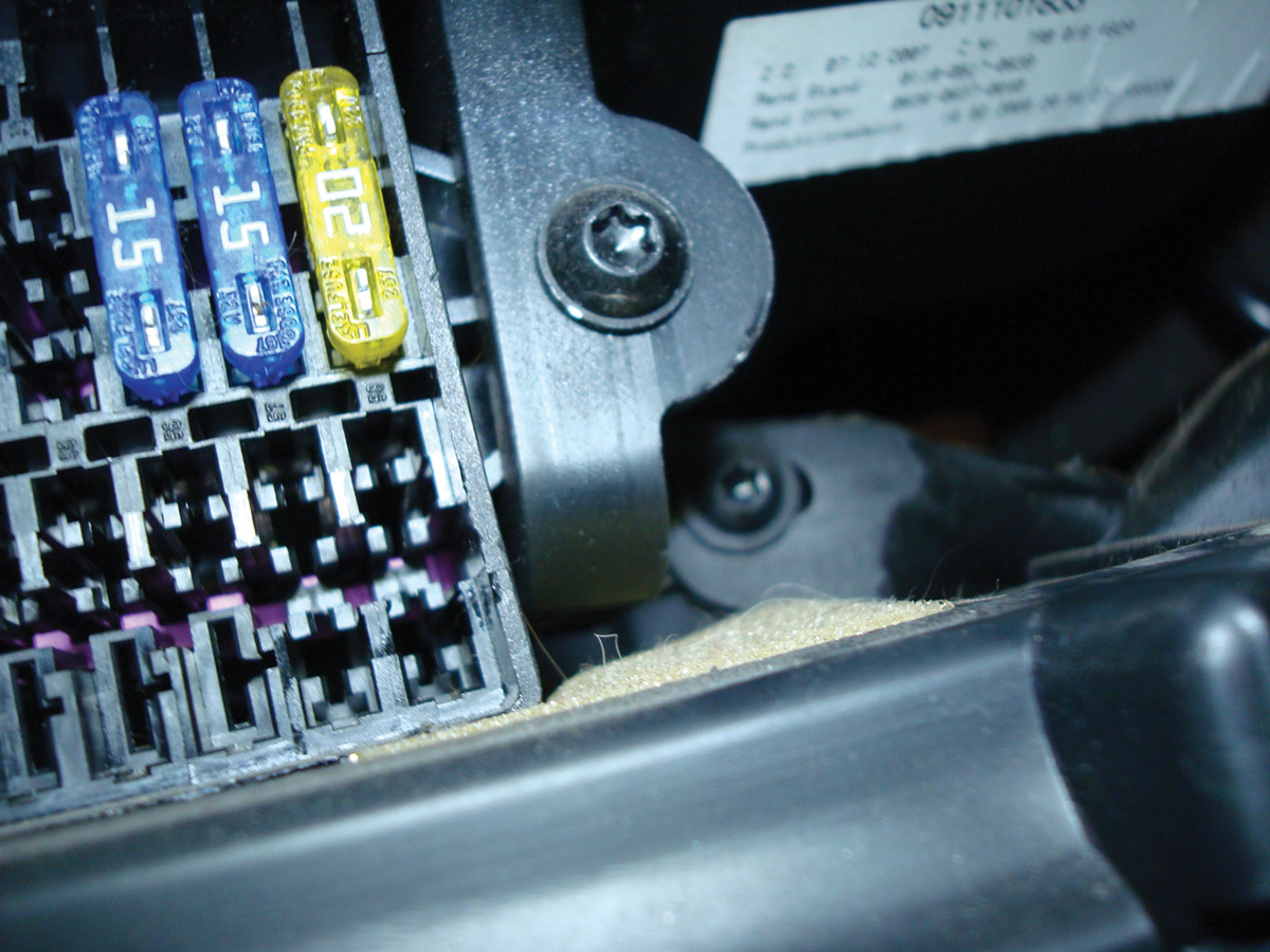
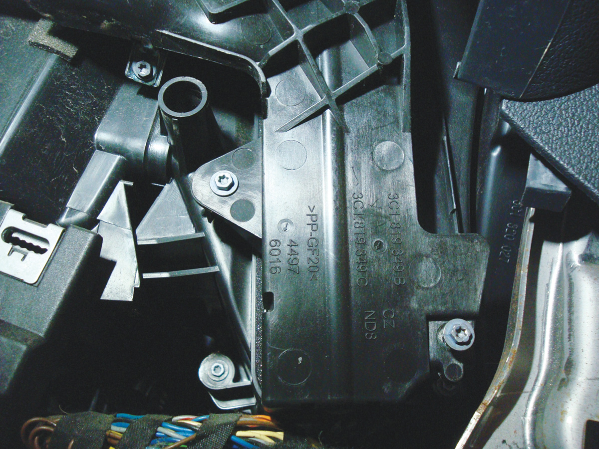
Remove the lower driver’s side cover and open the fuse box door. There is one screw to remove to drop/remove the footwell vent. This will expose the cover for the heater core and allow more room for heater core removal.
Make sure shop air is used to clear remaining fluid in the core and lay out towels to capture any dripping coolant when removing the core from the heater box.
NOTE: Do not damage the sealing foam from either core. Inspect the heater box interior for any debris and ensure it is clean. Also notice the heater split on the forward side of the core.
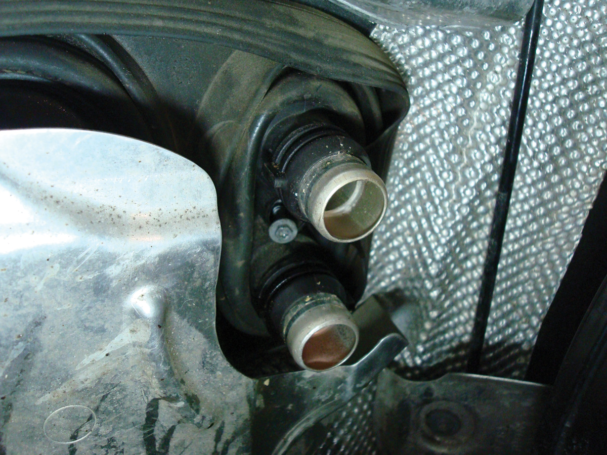
Remove the 4 screws and release the cover. Note the position of the tube clamps with the cover removed.
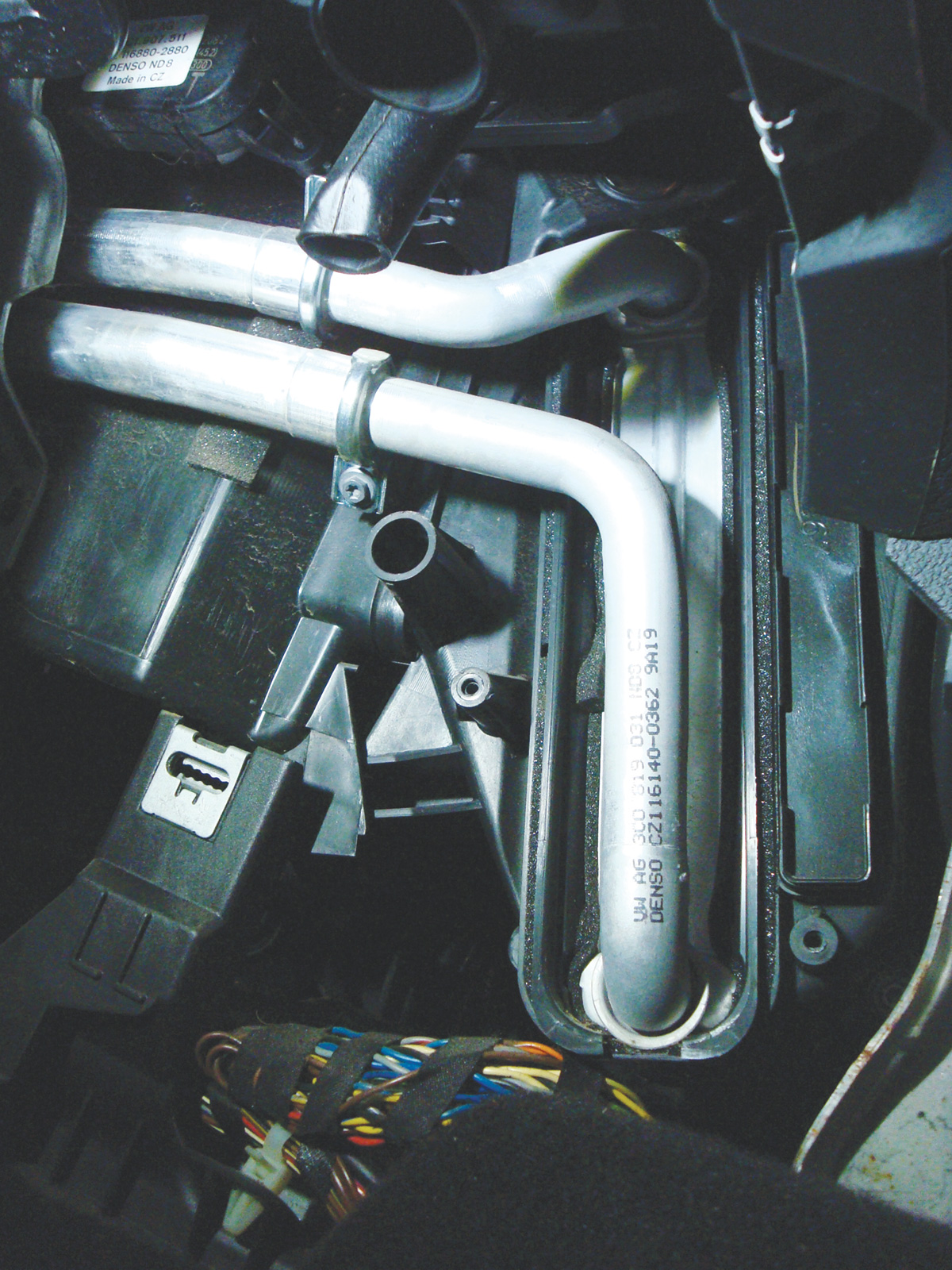
With the tube clamps removed, move to the front of the Tiguan and, with some slight force, move, wiggle, jiggle, swear, have a coffee break, and wiggle even more. The tubes need to clear the core. Do NOT hit, pinch, squeeze, bend, or pry on the tubes. Keep inspecting the movement of the tubes, and using a helper does go a very long way. If alone, it is not a race.
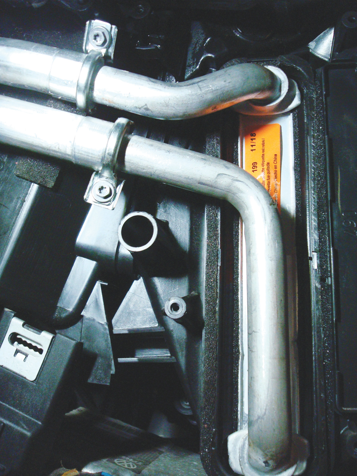
With some patience and a small amount of assembly lube, gently push the tubes onto the new core. Do NOT hit, pry, bend, or ram the tubes onto the new core. Pay attention to the o-rings and, if one tube is close enough to clamp, make it so. Continue with the remaining tube and follow the “Do NOT†part.
Align the clamps as viewed before disassembly. Leave the covers off.
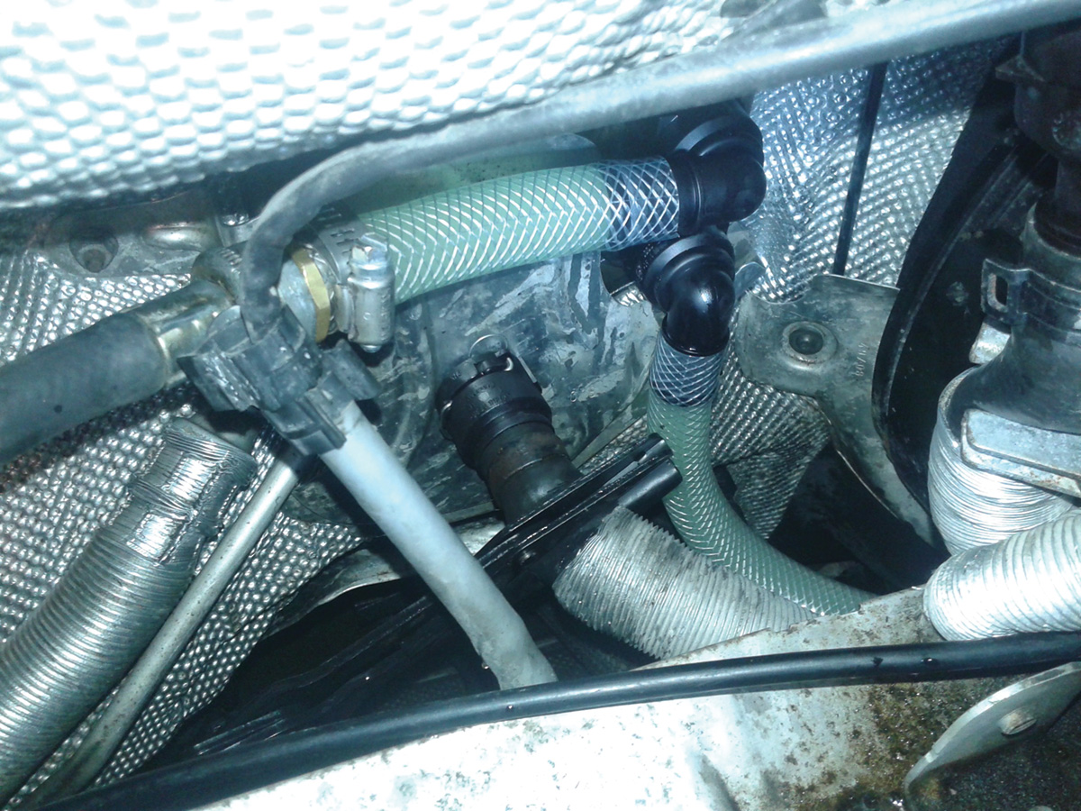
At the engine side, attach the screw at the heater hose couplers. Connect the heater hoses, remove the clamps and fill the reservoir. With some throttle applications, the core will bleed quickly. Monitor both sides of the vents. Monitor the temperature of the heater core tubes as well at the footwell. As the core bleeds air, touching the tubes will offer an indication of the coolant moving through the tubes.
Double check for interior and exterior for coolant leaks. Reassemble the heater core panels and covers. Double check the reservoir level and inspect the reservoir cap o-ring.
Re-check for faults and set adaptations/basic settings for the HVAC.
Cut open the core parallel to the tank and have a look inside. Inspect the goo or glue debris inside the core. Look at the bottom of the removed tank. It’s not impressive by any means but great for customer show and tell.
Remember to replace the coolant to G13 and measure the temperature on both side vents during the road test.
Was it a total failure?
Not when I can use the tool for similar issues and there is no goo or glue inside the core. The pump and solution appear to work great for future heater maintenance of any model. It did work on my A6 heater.
Would I attempt it again on a Tiguan of this generation? No!
It was faster to replace the core than attempting to flush/clear a poor design. A similar vehicle that is taking up space in the service bay while being flushed as in this example, is not profitable.
Remember: Search for all available TSBs and Dealer Campaigns associated with the vehicle.
NOTE: When using, applying, handling, and heating any chemicals in the work place or home environment:
- READ the warnings and labels on the container.
- Wear protective gloves, clothing and breathing masks.
- Ensure fresh air ventilation at all times.
- Have fire suppression equipment on hand.
|
Tools required: |
||
|
¾ inch ID clear plastic reinforced hose |
Ross-Tech VCDS |
I larger plastic pail |
|
12V electric water pump (garden hose attachment) |
Stainless mesh screen |
I smaller plastic pail |
|
Various ¾ OD threaded couplings (fast switch over) |
1 VW coupling |
90 amp power supply |
|
Water heater (WATLOW) to heat the solution |
ZEP (Calcium – Lime – Rust) solution |
Camera and clock |
|
CLR (Calcium – Lime – Rust) solution and NOT lemonade (debatable) |
1 VW coupling |
Gloves and mask |


0 Comments