
Use pre- and post-repair scanning to learn which Advanced Driver Assist Systems (ADAS) are on the vehicle, what fault codes have been stored, and how to avoid a few diagnostic rabbit holes.
Networked
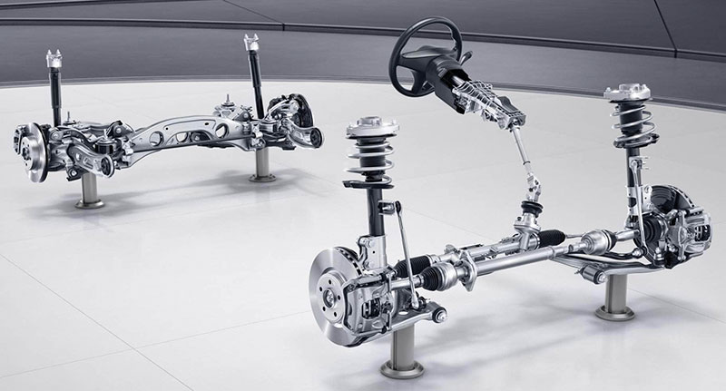
In today’s cars, everything is connected. Chassis control systems, including vehicle stability control, traction control, and anti-lock braking are networked together to improve safety. What began years ago as separate driver convenience features, such as electronic power steering and cruise control systems, are now combined with chassis control and sophisticated wiring technology to enable advanced driver assistance systems. Known as ADAS, these systems can adjust acceleration, steering, braking, and other functions independently if the driver is not responding to road conditions and outside threats in a timely fashion. Even power seats and windows, adjustable pedals, and power door locks automatically change to positions that improve the safety of vehicle occupants if a potential collision is nearing.
These are just a few of the many systems that are networked together to give the best fuel economy, emissions control, road handling and performance, and safety.
Act, observe, adjust
ADAS relies on a combination of state-of-the-art technologies, sensors to monitor what that hardware is doing, and software that allows computers to adjust the performance of a system or component, in real time, to enhance driver and occupant comfort and safety.
Collision connection
Many chassis control systems rely on inputs from sensors that are located near the vehicle perimeter, where they have a high vulnerability to collision impact damage. Wheel speed, yaw rate, ride height, and vehicle speed sensors all provide data to anti-lock braking, active suspension, stability control, traction control, and other road handling and driving performance systems. Damage to these sensors, their mounting hardware, wiring, and connectors may or may not be readily visible, but often sets fault codes. A pre-scan contributes to a more complete repair.
Thanks to controller area network (CAN) technology, a single sensor can share its data output with multiple vehicle systems almost simultaneously. Similarly, that data can be transmitted to multiple devices over a single wire (in reality, two wires twisted together, called a “twisted pairâ€). CAN technology and twisted pair wiring together make up the CAN bus network. The CAN bus allows digital signals to be shared quickly with every computer connected to the network.
Consequently, a failing sensor or defective wiring can affect several vehicle systems. If your collision damage assessment catches only one of the affected systems, you may replace a component that is a symptom, not the cause of the problem.
A diagnostic advantage
The CAN bus gives you a diagnostic advantage, if you pre-scan for fault codes before planning your repair. In addition to making it possible to use fewer wires to send sensor data and actuation commands to various vehicle devices, CAN bus wiring enables diagnostic communication.
For example, in addition to turning on the high beams upon driver request, the relevant control computer measures current flowing to headlamps on both sides. If one lamp is weak or burned out, the controller sees lower current and sends a problem identifier code via the CAN bus to all computers in the system. Each computer checks whether or not the identifier code applies to the system or components it controls. If it does not, the computer ignores the identifier message. If the message code does apply to a device that the computer controls, it stores a trouble code that can be retrieved from memory by a scan tool, and may also turn on a warning light in the dash. If multiple systems are affected, CAN bus diagnostics sends problem identifier messages that result in fault codes being set for any devices for which Mercedes-Benz engineers set up protocols for real-time monitoring.
A pre-scan collects and presents fault codes that highlight any systems in which problems exist and are monitored. This gives you a greater likelihood of identifying the cause and reducing the possibility of a comeback.
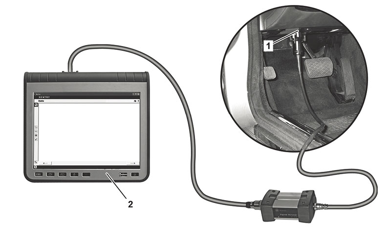
Of course, a factory scan tool covers far more fault codes than even a high-level aftermarket scanner. Many codes related to ADAS components are OEM-specific and can only be interpreted by a STAR DIAGNOSIS or other Mercedes-Benz diagnostic service tool.
A factory scanner also includes build data that an aftermarket tool does not. Build data helps focus your diagnostic efforts by telling you which ADAS technologies are on the Mercedes-Benz model in your bay.
Example: Lane Keeping Assist
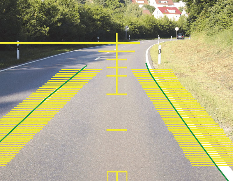
Mercedes-Benz Lane Keeping Assist (LKA) systems use real-time video images of where the vehicle is relative to lane markings in the road. When the Active LKA camera sees the vehicle traveling over the lane markings in the road, and warnings being ignored by the driver, the control module sends an actuation signal to another system to nudge the vehicle back on track.
Depending on how the model is equipped, the ADAS system may take over the anti-lock brakes (ABS) or electronic power steering system. The ADAS controller instructs the PCM to either command light pressure to the ABS on one side to pull the vehicle back across the line, or take control through the electronic power steering to turn the vehicle back to where it should be headed.
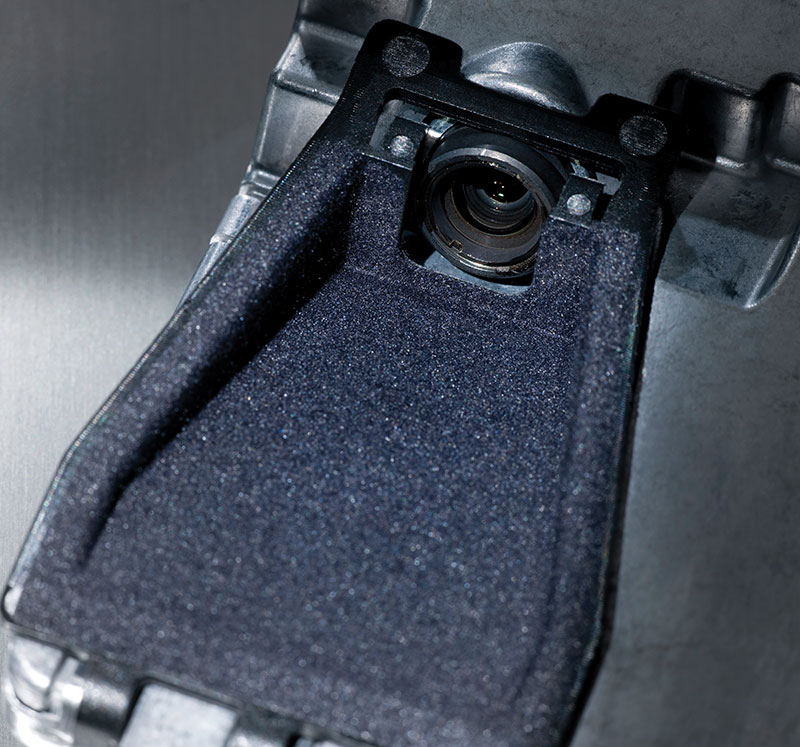
If the LKA camera has been affected by a collision, including damage to wiring, connectors, mounting brackets, or to the camera itself, the damaged part(s) must be repaired or replaced. Cameras that have been replaced or disconnected from power for any reason must be calibrated to ensure that they point in the correct direction. Calibration and re-initialization verifies that the control module can communicate with the camera, and knows its orientation.
Incorrect vehicle ride height, poor alignment, and other chassis control issues affect the accuracy of what the camera sees, and therefore the effectiveness of corrective measures commanded by the PCM. Whether the LKA system takes control through the electronic power steering or the ABS, any collision damage to those parts must also be repaired before full functionality is available.
You’ll find some of these potential problems in a visual assessment of damage. A pre-repair scan for fault codes helps catch issues that may be less obvious to the naked eye. If the vehicle is drivable, a test drive can help determine the level of functionality of many ADAS systems.
Example: Electronic stability program
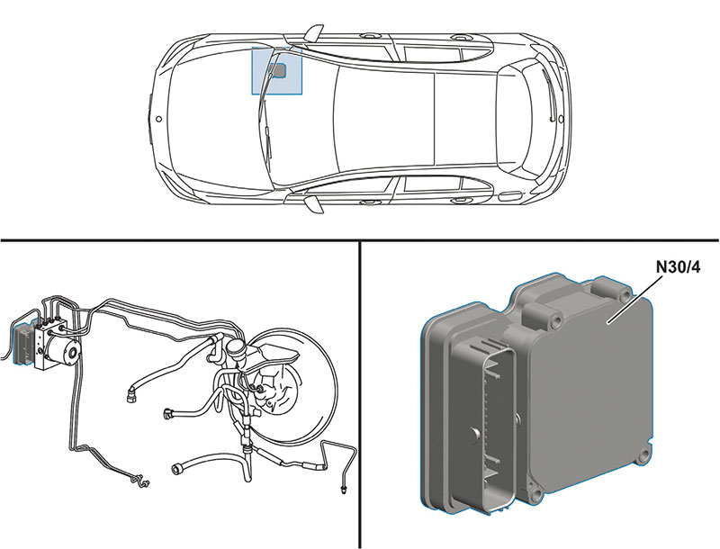
The powertrain control unit (PCU) sends commands to the electronic stability program (ESP), electronic brake force distribution (EBD), anti-lock braking (ABS), traction control, brake assist system (BAS), pre-charge brake, and many other systems, depending on the as-built features on the Mercedes-Benz model you are repairing. To do this, the PCU depends on inputs from the electronic stability program. The ESP control unit processes data from rpm sensors on all four axles, the brake vacuum sensor, stop lamp switch, accelerator pedal sensor, and other input sources.
The ESP control unit then transmits actuation signals as needed to the drivetrain control unit, supplemental restraint system (SRS) control unit, brake pedal signal, left and right electric parking brake actuator motors, and the electrical ignition lock control unit. If the PCU sees an out-of-parameter signal from any of the input sensors, or a component not responding within specification to one of the actuation commands, it stores a fault code for the affected sensor, component, or system.
Example: Adaptive damping system
Leaks or obstructions in air tubing, loose or failing height sensors, and damaged air springs are just a few examples of collision damage to air suspension components. But you must also consider the possibility of electrical problems in the control circuit, the compressor or vent solenoids, air spring solenoids, or the compressor relay.
The good news is that some Mercedes-Benz air suspension systems feature self-diagnostic capabilities. A pre-repair scan for fault codes helps narrow the diagnostic path so you don’t start replacing air suspension sensors or solenoids prematurely.
Changes to ride height affects caster readings. Out-of-specification caster readings lead to electronic stability control and steering problems. Checking ride height and air suspension dynamics is a good pre-alignment strategy.
Example: Bumper repair
The Parktronic system (PTS) is an ultrasonic measuring technology that detects distance to an obstacle. The PTS assists drivers in parking and backing up at low speed.
Parktronic sensors emit sonic signals that are reflected by nearby obstacles. The PTS monitors the amount of time it takes the reflected signal to return to the sensor and converts that number into a distance calculation.
The control module combines the distance calculation with data from wheel speed and steering angle sensors and presents visual and audio alerts to the driver as he or she moves near an obstacle. PTS fault codes may point to problems in receiving signals from these other sensors, damage to wiring, or related network issues instead of a failing Parktronic sensor.
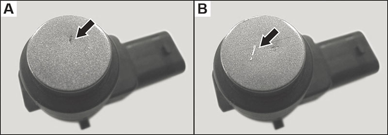
PTS sensors are mounted in front and rear bumper covers on many Mercedes-Benz models. If a sensor is soiled while driving through snow and ice, chipped by flying road debris, or impacted by collision it can suffer reduced functionality.
Fault codes, if set, tell you which Parktronic sensor to investigate further. For example, the fault code B1246 indicates that the Parktronic connector #A42b1 (left outer sensor, front bumper) has a problem. You must do further diagnostic testing to determine whether the cause is a loose or corroded connector, damaged wire, or failing sensor.
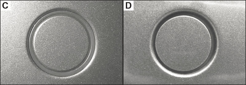
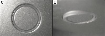
In some instances the system may not set a fault code. If the PTS does not store a fault code, careful pre-repair visual inspection of the wiring harness and sensor can identify damage. Even nicks and scrapes that appear minor can harm Parktronic sensor performance. Use close visual inspection to confirm correct position and angle of each sensor during replacement installation.
Because the PTS uses acoustic technology instead of a camera, painting the sensor surface may be allowed, depending on the vehicle model. Use of filler material over or near the sensors is not permitted. If your pre-scan indicates the presence of Parktronic sensors, check the repair instructions
to confirm whether you can paint over them and if so, the coating type and maximum thickness allowed.
Example: Headlamp variations
Don’t limit your repair planning to just scanning for fault codes. By looking up build data and searching through the Mercedes-Benz Workshop Information System (WIS) you can identify what ADAS technologies are on the vehicle. You can develop a list of what sensitive components may be located in collision-affected areas.
The identification codes used to catalog various advanced Mercedes-Benz headlamp technologies illustrate the benefit of checking build data. In addition to Static LED headlamps (all models with code 631), selected models have Dynamic headlamp systems (code 641), and Bi-xenon headlamps with integrated curve illumination (codes 615 and 616) as standard or optional equipment. Intelligent Light System (code 621) and Adaptive Highbeam Assist (code 608) are additional variations in headlamp control available on selected Mercedes-Benz models.

Dynamic lamps can also automatically adjust the amount of light based on vehicle speed. In stop-and-go traffic, the headlamps are activated at lower switch-on points to ensure that the cornering lights turn on early enough to cover the shorter turning radius of urban driving.
Dynamic lighting control uses inputs from wheel speed and steering angle sensors, as well as the turn signal function.
Fault code guidance
When pre-repair scan results do show trouble codes, do not automatically assume that an ADAS or other sensor is failing. A trouble code merely indicates that a reading from that sensor does not match the signal output specification expected by the controller. A code that says a signal is too low or high for a given circuit could mean that a sensor if faulty, but it could also be a short to power or ground due to impact damage or wear somewhere in that circuit’s wiring.
Physical damage to linkages, cables and hoses throw readings off even though the sensor itself may not be failing. For example, a fault code that reports a ride height sensor signal is a lower or higher value than expected may be the result of a broken mounting bracket.
Connected
Include pre- and post-repair scanning in every collision job. Connect to the information that helps you make complete repairs and return the vehicles you work on to like-new condition.
Download PDF


0 Comments