
What were once just chunks of rubber and steel have now become complex and active. Expect bad vibes, noises, and spreading fluid when they deteriorate.
“Isolate.†The Oxford dictionary defines this as “…to cause (a person or place) to be or remain alone or apart from others; To identify (something) and examine or deal with it separately.â€
When we think of motor mounts, we often think of metal cups with rubber between, something for the engine to sit on. But today’s motor mounts are quite a lot more than that: Not just fluid-filled, but active and electronically-controlled. Let’s take a look at some of the newer technologies of the humble motor mount.
Motor (or engine) mounts have been in place for years to “isolate†the engine vibrations from the rest of the vehicle. I remember an older Norton motorcycle I owned when I was much younger that touted what was called “isolastic engine mountsâ€, using a play on the words isolate and elastic to describe what the engineers had designed to smooth the ride of the bike.
Motor mounts not only support the engine and transmission but also dampen noise, vibration and harshness (NVH). The mounts isolate the engine and transmission from the chassis so that vibrations and noise are not transmitted to the rest of the vehicle. Since the power plant is the largest concentrated mass in the vehicle, it must be properly constrained and isolated or it will cause vibrations in the body.
If you think about it, you have all kinds of motions and energies generated during the combustion process. Pistons are traveling up and down, exploding fuel energizes and spins the crankshaft, cams and valves bounce along. Torques and other forces are applied through the drivetrain to the wheels. Now add road forces, pavement imperfections and dynamic motions as the vehicle travels down the road, coupled with the weight of the engine and its lateral forces, and it is easy to see the that the motor mount is one of the hardest working components of the modern automobile.
History and the earliest mounts
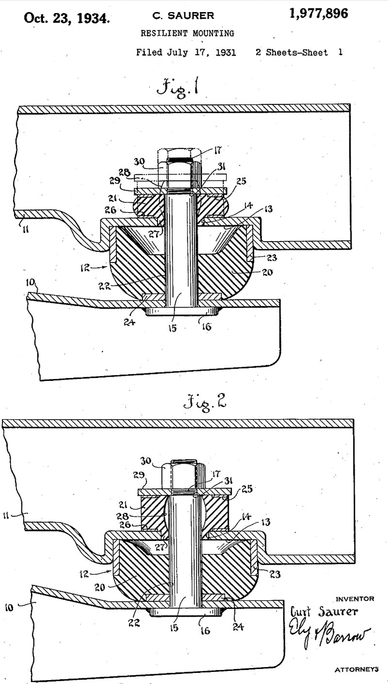
The details of early motor mounts are a little fuzzy as to exact vehicles and ideas but one thing is certain: All the early mounts used a type of rubber or elastic material that has some flex or “give†to it, sandwiched in between two pieces of metal, fixing the power plant to the frame. An early patent granted in 1934 to Bridgestone Firestone Inc. has a mounting system described as: “springs made of rubber or other material having high internal friction, e.g. thermoplastic elastomers characterized by the mode of stressing loaded in combined stresses.â€
The earliest automobiles simply had the engines mounted directly to the chassis of the vehicle. These cars or carriages did not have much horsepower, torque or even much of a suspension, and the ride of the vehicle certainly was not of much concern, although better than the horse and buckboards. As cars developed much more powerful engines the need for isolation became evident.
The Need for Improvement
The obstacles that engineers are faced with solving are described in physical terms as:
- Low frequency (1-50Hz) and high amplitude (1-2mm) vibration from shock excitations. Shock excitations are caused from driving on uneven roads, or from sudden vehicle acceleration or deceleration.
- High frequency (30-250Hz) and low amplitude (0.005-0.5mm) vibration from unbalanced engine forces. Unbalanced engine forces are caused from the firing pulses, and from any mass imbalance that exists in the rotating and reciprocating engine parts (e.g. in the piston, connecting rod, crank, etc.).
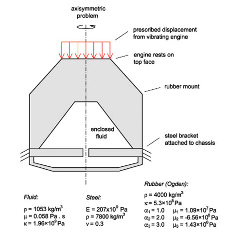
To solve this problem, Mercedes-Benz engineers began to use hydraulic, or oil filled, motor mounts. To isolate the chassis from the unbalanced engine forces, the mount must be soft and lightly damped in the high frequency range, but to prevent the engine from bouncing under shock excitation the mount must be stiff enough and highly damped in the low frequency range. If the engine bounces with large amplitude under a shock, the engine components and surrounding vehicle structure can be damaged.
Since these two requirements are in conflict with one another, the dynamic stiffness and damping of the engine mount needs to be frequency-dependent. Hydraulic engine mounts can be highly tuned to approach an ideal stiffness which satisfies these two requirements. These mounts are much more effective than conventional elastomeric mounts whose dynamic stiffness does not readily change or adapt to the frequencies described above.
Genuine Mercedes-Benz motor mounts have been engineered to a specification that conforms to the optimal stiffness and vibration coefficient in order to give your customers the smoothest ride characteristics. Dozens of Mercedes-Benz engineers spend a not-so-small fortune testing motor mounts to ensure they are the very best possible. Cheap aftermarket mounts may look the same, but their manufacturers often cut corners and their product will fail to meet the rigid performance and longevity specifications that Mercedes-Benz demands.
Symptoms of Faulty Hydraulic Mounts
When diagnosing hydraulic mounts there is really only one obvious difference to solid mounts: the hydraulic fluid. Symptoms of faulty or failing mounts are:
- Excessive vibration. The customer may have a complaint that they are feeling more vibration than normal, especially at idle. Some may say that the engine is running rough. Sit in the driver’s seat at idle, change the engine speed a little, and engage drive or reverse to note changes in frequency or harshness of the vibration. Sometimes the passenger feels it more.
- Noise. Excess noise such as knocking or clanking sounds from the engine compartment may be an indication that a mount or mounts are broken.Â
- Misalignment. As described above, part of the mount’s job is not only to fasten, but to also align the engine and drivetrain in the vehicle at proper angles for optimum performance. An engine that is not level, or tilted at odd angles, is a giveaway that something is awry.Â
- Broken or stressed hoses. Since we talked about how an engine mount aligns the power plant with the chassis, a broken or failed mount can lead to excess stretch of certain hoses. Too much strain can tear the hose, disconnect it or break off an attachment point.
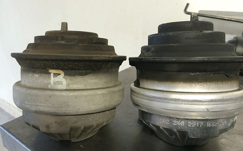
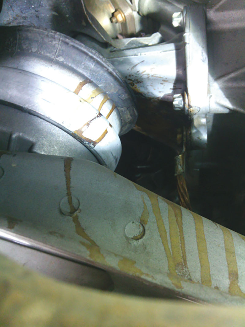
- Fluid leaking. Lastly, the main difference as we mentioned is the hydraulic mount has internal fluid. Oil residue on the engine below the mounts or dripping on the ground can be a symptom of a failed mount.
Active mounts
The “fixed tuning†of a typical motor mount is a compromise, to balance noise, vibration and harshness across a wide range of operating conditions. But when technology presents a new solution to a problem, Mercedes-Benz is at the forefront. Enter the active motor mount.
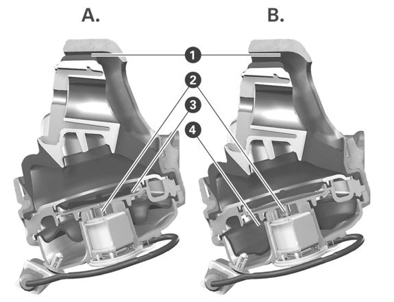
Electronically switchable motor mounts increase the possibilities of conventional hydraulic motor mounts. If you take a conventional hydraulic motor mount and add to it an actuator valve, some sensors and a control unit, it can be actively controlled, perfectly adaptable to any situation.
Depending on the motor excitation frequency, the motor mount dampens either hydraulically, passively or actively. The isolation characteristic is calculated by the control unit and converted by the actuator so that virtually no vibration is transmitted to the chassis of the car.
The advantages of active hydraulic dampening are:
- Improved vibrational comfort
- Improved high frequency behavior
- Customizable set-up of the mounts in terms of rigidity, damping positions, and neutral position behavior
Mounts Continue to Evolve
Further along on the technology scale are the second-generation magneto-rheological engine mounts used in the Mercedes-AMG C 63 S, for example. Unlike conventional hydraulic mounts which provide peak damping at a single frequency and amplitude, or the complexity found in actuator-valve motor mounts, the Magneto-Rheological (MR) Powertrain Mounts can provide high damping over a much broader frequency and amplitude range.
Using a special magneto-rheological (MR) fluid to change the damping rate in real time, these powertrain mounts may be “firmed up†with high levels of lateral acceleration for more direct cornering, or “softened†for maximum comfort during straight-ahead driving. Furthermore, the combination of precise control of powertrain motion with substantial elimination of noise and vibration simultaneously improves vehicle stability and interior comfort.
The mount contains an electromagnetic coil that can generate a variable magnetic flux across the fluid passages. When the coil current is turned off, the MR fluid is not magnetized, the iron particles are randomly dispersed within the fluid, and the fluid behaves like conventional hydraulic oil. When the coil is energized, the magnetic field causes the particles to align into fibrous structures in the direction of the magnetic flux. The strength of the bond between the particles in the structures is proportional to the strength of the applied magnetic field, so changing the current provides real-time variable damping with a very large range of force variation.
Testing – Diagnosis – Repair
After verifying your customer’s concern you can begin the process of repair and replacement of faulty components. Remember, no matter what type of mount you have, start with the basics: Most failures are going to be mechanical in nature. Torn elastic and leaking fluid will be the top culprits.
Begin with a visual inspection: Is the motor level and sitting at the right height? Raise the vehicle and look for signs of stress in the mounts or uneven spacing. Inspect the mount thoroughly for leaks and torn rubber. Some mounts may have obvious active leaks, but you may have one that has leaked for some time and now is empty. Check for staining around and below the mount for evidence.
Use a pry bar or lever and check to see if you can lift up one side or the other of the mounts. Use care in this procedure to not damage any other components. Don’t forget the rear mount at the transmission.
Have an assistant power-brake the engine slightly, and look for excessive movement or lifting of the engine. Active motor mounts can set a code in the control unit, so perform a XENTRY Diagnostics quick test. You may find codes for circuit faults, short to positive, short to negative, and internal electrical faults as well as others.
An example is DTC P0AB649: Actuation for engine mount B has an electrical fault or open circuit. XENTRY would then guide you to identify the exact fault by testing the circuit, wiring, motor mount, and related components.
Replacing motor mounts is generally straightforward. Follow the work instructions in the Mercedes-Benz Workshop Information System, even if you think it’s just a bolt-on part. Some of these newer motor mounts have special needs and procedures. Also be sure to have proper equipment to support the engine as you remove the mounts. A screw or transmission jack can be helpful in this repair.
Some models require the removal of components to provide clearance. In some cases on a 4MATIC you have to drop down the front axle. It is always a good idea to check STAR TekInfo for any possible updates or bulletins addressing the customer’s concern on the vehicle. Sometimes you may have a complaint of a vibration or noise but the mounts appear perfectly normal. This can be due to the actual alignment of the mounts in the vehicle. The following is a service bulletin with exactly this problem and the solution is a simple adjustment of the mount.
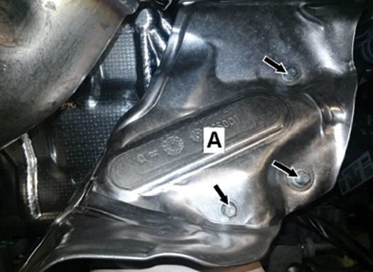
When repairing or replacing mounts you will almost always find a heat shield of some sort protecting the mount. Invariably engine mounts are often in the vicinity of the exhaust system or other hot components and need to be protected. Be sure to examine these closely to be sure they are in good shape. If not, order up a new one to protect that new mount.Â
Download PDF


0 Comments