
How a Seemingly Simple Radiator Replacement Leads to Three Weeks of Technician and Customer Frustrations
As technicians, we can all identify with that one vehicle that seems to twist us into knots, that vehicle where a seemingly routine, simple repair turns into a diagnostic disaster. A recent support call revealed such a case. This month’s article features said vehicle and what was required to “untangle†the diagnostic mess.
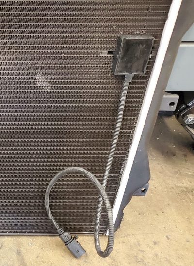
Consider that you are working on a 2012 Golf GTI with a 2.0L TFSI (CBFA engine). The customer presents at the shop with a coolant leak and a Check Engine light on. You pull the vehicle into the bay, visually inspect the engine compartment and hook up your trusty coolant pressure tester to check for leaks. In this case, you very quickly see the problem; a gnarly coolant leak at the radiator’s tank where the core and tank come together. The DTC is a P2568, indicating the Direct Ozone Reduction Sensor.
Ha! This will be a gravy repair, a fairly routine diagnosis and repair, right? Yea, right. Not this one…
Here, the technician replaces the radiator, refills and bleeds the cooling system, clears the DTC then road tests and releases the vehicle back to the owner.
Three days later, the customer returns to the shop and complains that his Check Engine light is illuminated again, but at least the coolant leak is solved.
You bring the vehicle into the bay to evaluate the light, hook up your scan tool and pull a DTC P2568. The code description simply says: P2568 Direct Ozone Reduction Sensor, no other description provided.
You look up service information, and there is little actionable information available for this DTC. You research this further and determine that the sensor, (mounted to the radiator with glue and clips) is actually an anti-tamper sensor for the Direct Ozone Reduction radiator. The new radiator came with a new sensor, but you had to glue the sensor to the radiator when you installed it the other day. You ask yourself, what could have gone wrong here?
During the diagnosis, you also notice there are no associated data PIDs for this sensor, the wiring and connector look fine physically (they are properly connected, no wire pinches, cuts), so you prudently hook up your lab scope to the sensor in order to verify that the sensor’s power, ground and signal circuits are intact and functioning properly.
Why the scope? Because the sensor is not diagnosable with the scanner (no PIDs or data for this sensor, remember?). The scope check proves the actual circuits are, in fact, working properly, so you re-set the CEL, drive the car and give it back to the customer once again.
Three days later… Its BAAAACK! To make a long story short, this happens a third time as well. Now, you need to get a bit more serious on how to resolve this code, it is NOT going away magically.
Upon scope checking the physical sensor again, you notice that the power and ground circuits are working properly. You have full voltage, no voltage drop on the ground circuit, and then the signal circuit catches your attention. It seems that the “sensor signal†circuit is actually signaling more like a communication line, rather than an analog sensor return circuit. Huh? Interesting!
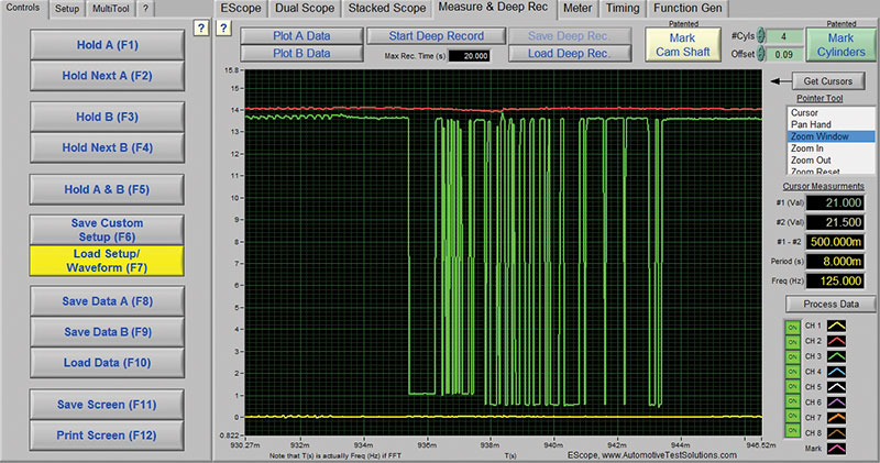
Note the power, ground and signals are occurring properly, the sensor seemingly works fine.
Wait… Why would we possibly need an “anti-tamper†sensor for a simple coolant radiator? And furthermore, what the heck is a Direct Ozone Reduction radiator?
Upon further research, you are learning that on certain California emission equipped vehicles, there is actually an emission control device built into the radiator assembly. Wow. How does THIS work, you wonder, and how does this relate to my Check Engine light?
You learn that the system is called Prem-Air, originally designed by Engelhard Corp, a New Jersey chemical and catalyst manufacturer in the late 1990s (now BASF of Germany) and the device is designed to reduce ground level ozone gases as the vehicle drives down the road.
NOW, you are intrigued.
Let’s do a deep dive into this technology and see how it works. With a more in-depth understanding of the system theory and, more importantly, the sensor involved, we can untangle the diagnostic mess.
Engelhard/BASF’s Prem Air Technology Overview and Operational Theory
Back in the 2000 model year, Volvo first introduced the Prem-Air technology on a few of its models. The Prem-Air technology is pretty cool; it is designed to convert ozone gas to oxygen as air passes over the radiator while you drive.
Ground level ozone reacts in combination with sunlight, combines with exhaust NOx and NMOG (Non-Methane Organic Gases) such as hydrocarbon particulate matter, and this chemical reaction creates smog. If we can reduce the ground level ozone, there is less reaction with the sunlight and gases, therefore, less smog is formed. Brilliant!

This inventive technology works on a fairly simple principle. The radiator is coated with a catalyst material similar to that used in the catalytic converter, but using different precious metals. The theory is that this catalyst coating, when heated to the correct temperature, will convert the ozone (O3) molecule to an oxygen (O2) molecule, so that the ozone coming across the front of the radiator becomes harmless oxygen on the other side of the radiator as it is driven.
Several manufacturers since Volvo, namely VW/Audi, Mitsubishi, Mercedes-Benz, BMW and others have adopted this technology, mainly because CARB allows for higher Tier 3 emissions credits to the manufacturer for having this technology on board.
The “light-off†temperature for the catalyst material occurs at approximately 60 degrees C (140 degrees F) to 75 degrees C (167 vegrees F). Once at light-off, this catalyst begins chewing on ozone molecules as you drive. The stated effectiveness, according to OEMs’ long-term studies, is between 45 percent and 75 percent conversion.Â
The actual conversion is dependent on several mitigating factors, for example:
- Whether the vehicle is equipped with the first generation catalyst coating, vs. the new generation BASF Prem-Air NXT, their new, more robust catalyst coating.
- The surface area of the actual radiator (more surface, more conversion), and…
- The speed of the vehicle. The catalyst will convert more gas at lower speeds due to the time interaction with the catalyst surface as air passes over the core, so therefore conversion decreases as the vehicle’s speed increases.
Now, for the sensor part
The California Air Resources Board (CARB) required a way to verify that the correct radiator with the catalyst is installed and functioning on the vehicle in order to receive the additional emission credits, so they mandated that OEMs would be required to integrate a feedback sensor to the OBD II system AND provide tamper-proof circuitry to make sure nobody could change the radiator to one without the coating. Otherwise, there would be no way to verify if any replacement radiator contained this emission device.
The mandate also required that the OEM make the sensor fully tamper-proof, meaning ANY attempt to remove, or re-locate the part would result in “physical and electrical†destruction of the sensor. Another design requirement was to make it so that the sensor could not be bypassed and “fooled†by a tech replacing the sensor with a resistor, or by designing his own work around.
The result of this design was that, rather than making the sensor’s thermistors report an analog voltage to the ECM as other temp sensors do, these sensors (G-611) are designed as a LIN Node, the sensor receives and processes its signal from the sensors internally, then configures an encrypted LIN message to tell the ECM two specific things:
- LIN packet reports the two separate internal coolant sensor’s information to the ECM, and…
- Sensor transmits a unique encrypted message over the LIN bus verifying that the correct sensor and radiator are installed (and working).
Huh? So, how would a technician diagnose this sensor? You don’t. According to service info, once you have verified that the power, ground and LIN wires are OK and signaling, you replace the radiator and sensor. That’s it. There’s nothing else a tech can “see†based on the fact that the sensor’s info and encrypted verification message are sent over data bus, there’s nothing else to look at for diagnosis of the system. At least, that is what we are told…
A Google search on this will reveal that many techs, including in the dealerships, have had to replace multiple radiator/sensor combinations in order to get the light to go out.
To be clear here, this system has zero implications as to the way the car runs, nor in the performance of the cooling system itself; if this system fails, the vehicle will not experience any negative driveability effects. BUT, the Check Engine light will illuminate and, until repaired, the vehicle will fail a state emission test, especially in IM 240 states where the only emissions test is an OBD II monitor check for inspection.
By the way, the radiator and sensor must BOTH be replaced at the same time. Because the sensor is tamper proof, there is no practical way to separate the two to replace one or the other. Therefore, just a simple sensor failure here means that the radiator needs to be replaced also.
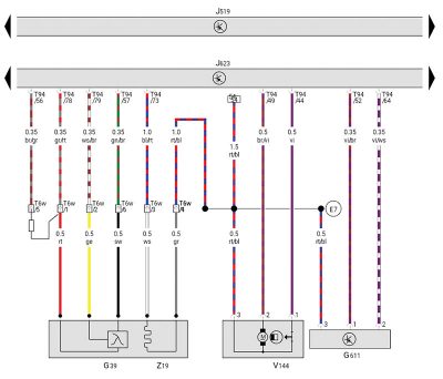
A look at the wiring schematic for ATD Radiator Sensor G611 shows a three-wire sensor circuit.
Pin 1 of this sensor is a violet/brown wire, which on this Golf GTI/CBFA engine, goes to connector T94 at pin 52 of the ECM. This wire serves as sensor ground at the ECM.
Pin 2 of the sensor is a violet/white wire, which is a LIN bus communications line, going to connector T94 pin 64 of the ECM.
Finally, pin 3 of the sensor goes to a splice, which connects directly to the O2 sensor heater power circuit and carries battery voltage; this wire terminates at a splice point. (note: These pin assignments are for this particular vehicle; consult schematics for different years/models).
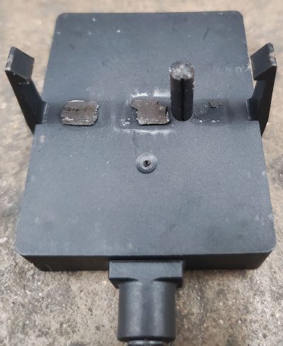
The sensor body itself is made of a brittle, thin poly plastic, designed to physically break if pried, twisted or tampered with in any way. The electrical circuits are also designed so that if the sensor body breaks, the internal wiring breaks as well, rendering the sensor useless.
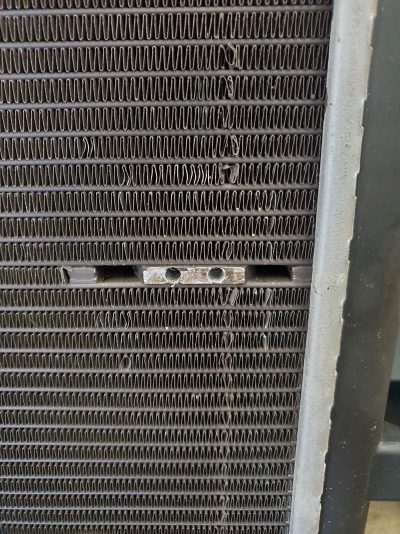
In addition, this sensor is mounted onto a unique heat sink built into the radiator core with a recessed hole for the coolant temp probe. (See Ozone Reduction Radiator on page 2.)
You will notice that there are three distinct contact points on the heat sink. This is where the second internal coolant sensor is close-coupled to the heat sink, so as to be able to sense the temperature of the heat sink. The first sensor is in the probe tip that goes into the heat sink hole and measures the coolant temp in the radiator.
According to several patents researched, there are actually THREE coolant sensors in play for this system. The first two are located in the ATD sensor itself, the third is the ECT, upstream of the thermostat.
Theoretically speaking, the way the system works is that the coolant temperature is measured at the radiator (probe), the heat sink temp is sensed by the internal sensor, and these readings are configured in a LIN message within the sensor, combined with the encrypted verification message and sent to the ECM via LIN packet.
Inside the ECM, this information is processed and correlated to the engine’s ECT and then is run through the ECM’s truth tables and algorithms to determine a good or bad signal from the ATD sensor on the radiator. If all is normal, no light.
To understand this system further, let’s look at the codes that could potentially set related to this system. Audi’s PDF on the CBFA 2.0L GDI engine shows us a list and description of the codes possible.
- P2568 Direct Ozone Reduction Sensor Implausibility (the code setting in this case study)
- P2569 DOR Sensor Short Circuit
to Ground - P2570 DOR Sensor Short Circuit to Battery/Open Circuit
- U102E LIN Message Incorrect Signal Implausible (indicating an internal sensor problem)
- U102F Timeout, No Communication
- U1030 LIN Bus Inactive
OK, now it can be understood from the outlined theory and the code list that beyond checking pin 1 for the ground signal, pin 2 for proper LIN activity and pin 3 for power from the O2 heater circuit, there are no real “repairs†a tech can make here.
So, why the multiple replacements in this and other cases, you ask?
Upon researching all of the above information and determining that the circuits worked and, verifying no physical damage to the sensor itself, the answer was found in the patent research.
In calculating the time and temperature differences needed to set the DTC, it was found that the three coolant sensors could not be more than 41 degrees F away from one another over an 800 second test from cold start correlation.
Note that during warm-up, there are three things being looked at here by the ECM. First, the ECM watches both the coolant temp sensor (ECT) and the radiator probe portion. This helps the ECM to confirm proper cooling system operation, and helps verify that the thermostat actually opened. Second, the heat sink sensor tells the ECM that the radiator catalyst material is able to reach “light-off†temp (greater than 140 degrees F) and, lastly, the encrypted verification message sent in the LIN packet is either accepted or rejected by the ECM.
So, if any of the temperature signals vary more than (approximately) 5 degrees C (41 degrees F) from pre-set thresholds within 13 minutes from cold start, the DTC P2568 Implausibility code will set. If the LIN encrypted message is not accepted, a DTC U102E LIN Message Implausibility code will set.
So after gaining all of this lovely knowledge, what actually fixed this case study?
The gluing procedure. That’s right… the gluing procedure was causing the issue. If one were to look up the Volkswagen/Audi service info on this, one would observe that they want the glue applied to one specific portion of the new sensor, the PROBE portion only.
This figure shows the area of the probe where the glue is to be applied. Do not apply adhesive to the face or body of the sensor, or you may create the problem outlined in this article!
What was happening was that the technician was applying the adhesive to the face of the sensor body, not the probe. This created a solid film barrier between the close-coupled sensor body and heat sink.
The additional glue barrier provided increased insulation and distance between the sensor and heat sink, skewing the temperature curve during warm-up by greater than the allowed 5 degrees C, thus setting the plausibility code.
Der Fix? Glue the new sensor carefully according to directions, and there are generally no further problems, provided that one does not crack or break the new sensor while pushing it into the heat sink and engaging the clips.
Just goes to show you that sometimes, it DOES pay to read the directions.
Moral of the story?
Don’t be “That Guy.â€
Download PDF


0 Comments