
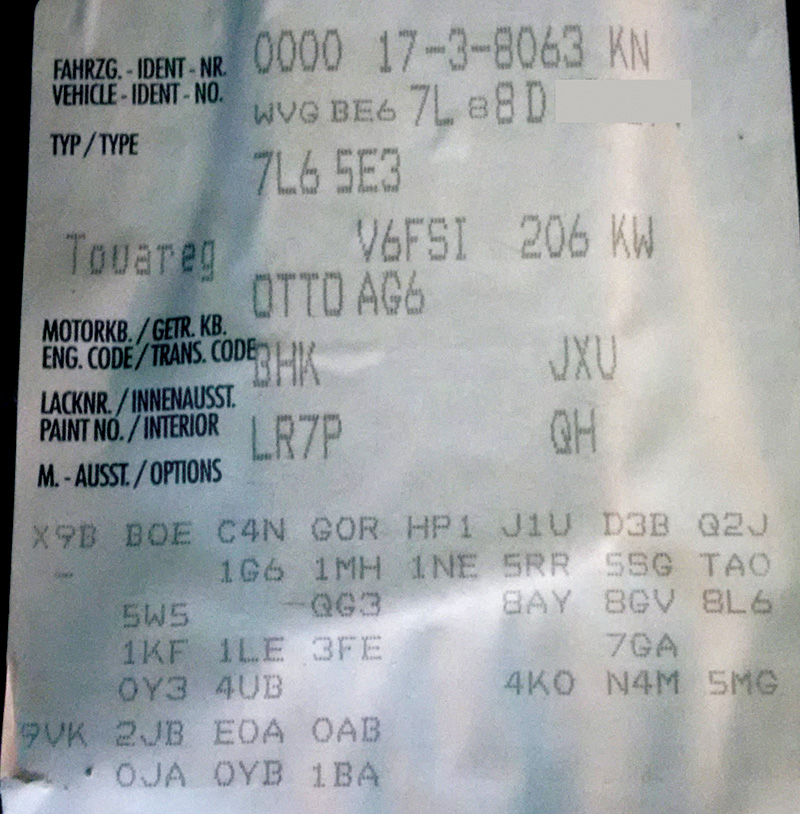
The victim is a 2008 Touareg with VR6 FSI, 09D automatic with 4-wheel drive
History
The customer asked an odd question during a phone conversation: “Why would the transmission downshift abruptly when driving?â€
| Tools Used |
| VCDS with a 90 amp power supply |
| ElsaWin diagnostic information |
| Screen capturing and movie capturing software |
| Pen and paper with a simple camera |
| Plastic trim tools with hooked tools |
Start with a scan
When visiting the facility, the entire scan was saved and faults deleted. (See “Scan results.â€)
| Address 02: Auto Trans Labels: User\09D-927-750.lbl |
| Part No SW: 09D 927 750 GD HW: 09D 927 750 ER |
| Component: AL 750 6A 1093 |
| Revision: 00H61000 Serial number: |
| Coding: 0004216 |
| 1 Fault Found: |
| 01045 – Tiptronic Switch (F189) 008 – Implausible Signal – Intermittent |
| Freeze Frame: |
| Fault Status: 00101000 |
| Fault Priority: 2 |
| Fault Frequency: 1 |
| Reset counter: 197 |
| Mileage: 148117 km |
| Time Indication: 0 |
| Fault Priority Numbers | |
| No. | Meaning |
| 0 | Undefined by manufacturer. |
| 1 | The fault has a strong influence on driveability, immediate stop is required. |
| 2 | The fault requires an immediate service appointment. |
| 3 | The fault doesn’t require an immediate service appointment, but it should be corrected with the next service appointment. |
| 4 | The fault recommends an action to be taken, otherwise driveability might be affected. |
| 5 | The fault has no influence on driveability. |
| 6 | The fault has a long term influence on driveability. |
| 7 | The fault has an influence on the comfort functions, but doesn’t influence the car’s driveability. |
| 8 | General Note |
The freeze frame option with the scan tells an interesting story about the fault and the concerns the vehicle owner is experiencing.
Fault Frequency: Indicates the number of times the conditions that caused the fault have repeated during all driving cycles. This specific frequency occurred once and the customer called immediately, having the fault addressed the next day. The fault counts from 0 to 254 and increases with each drive cycle occurrence.
The Reset Counter is preassigned to each fault. If there are fault free driving cycles and the fault does not return, the counter will reset to the next lower number with every key cycle.
Since the scan was saved and deleted, some simple measured values were read and tested while driving. It is NEVER a good option to read data and drive a vehicle, and the immediate choice was to use Camtasia® to record the screen activity and include any noise or voice recordings. Saving each recording during the process offers a great method of diagnosis when alone and during an extended drive. These saved recordings are great for playback to test for anomalies and for the customer as well.
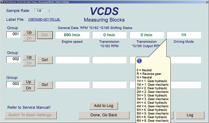
As with any road test of this nature, the primary group 001 with field 4 will offer the shift points as the vehicle is driven on surface streets or a highway course. This test had access to both in very close proximity.
A well made label will offer the specifications attached to a field. In this case field 4 offers the changes as the transmission engages the specified gear during the road test. Note as well, the image and test is at a standstill/idle speed.
So what else can be noted during the test?
There are a number of groups that can be tested during the drive. Inputs and outputs can be viewed with either a second technician or with screen “movie†capturing software that can be saved and played back.
Of interest and testing the shifter circuit board, the choice was 001, 004, and 012.
All three groups should be accessed to help determine the possible fault.
An explanation of the VCDS images
| Group 001 is basic information that reads the status of: |
|---|
| Field 1 Engine rpm |
| Field 2 Sensor G182 as Transmission input rpm |
| Field 3 Sensor G195 as Transmission output rpm |
| Field 4 Is the actual gear the TCM has actuated |
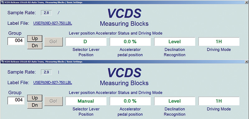
| Group 004 is basic information that reads the status of: |
|---|
| Field 1 Is the transmission lever position in D or Tiptronic |
| Field 2 Accelerator position in percentage |
| Field 3 Calculated inclination (uphill or downhill) |
| Field 4 Is the actual gear the TCM has actuated |
| Group 012 is basic information that reads the status of: |
|---|
| Field 1 Is the transmission lever position in D or Tiptronic Mode |
| Field 2 Will be the shift level be pushed down or up in Tiptronic Mode |
| Field 3 Is the actual gear the TCM has actuated |
| Field 4 Torque Limitation is the change in transmission torque (test while driving) |
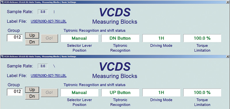
With these three groups, the majority of inputs and outputs can be tested and be forced into conditions that will measure the activity of Tiptronic Switch (F189).
So what happened?
With the surface and highway test, and with our being a little rough with the shift lever, nothing happened!
All data was normal and the technician took the time to view the recorded images and videos.
When facing an evolutionary mistake, one might wonder, “Can I have my sixty seconds back?†In this case, 1.5 total hours was the time it took to have no faults recreated.
With a clean scan and no faults recorded in history, the best option is to have the customer drive the vehicle. The instructions were, “Call the lab immediately†if the Touareg downshifts unexpectedly and make sure it is in D at all times.
Testing a schematic with the saved images led to the second test and part two of the anomaly. The customer mentioned one forgotten detail: “The Touareg was pulled over to the shoulder of the road and I cycled the key†to have it back to normal driving.
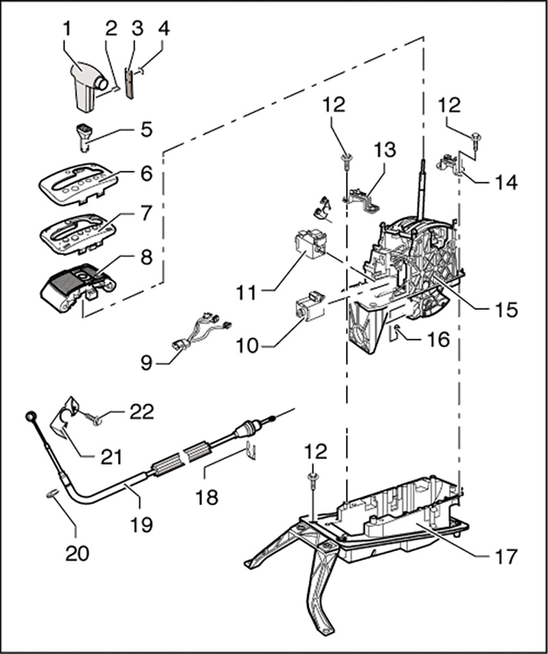
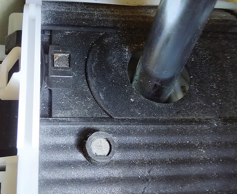
F189 is indicated at number 7 and referred to as a “Printed Circuit†board. At number 8 is the rubber sliding cover with two embedded magnets. The magnets move with the rubber sliding cover, activating microswitches within the printed circuit board. The micro signals and lever positions are processed and sent to the TCM.
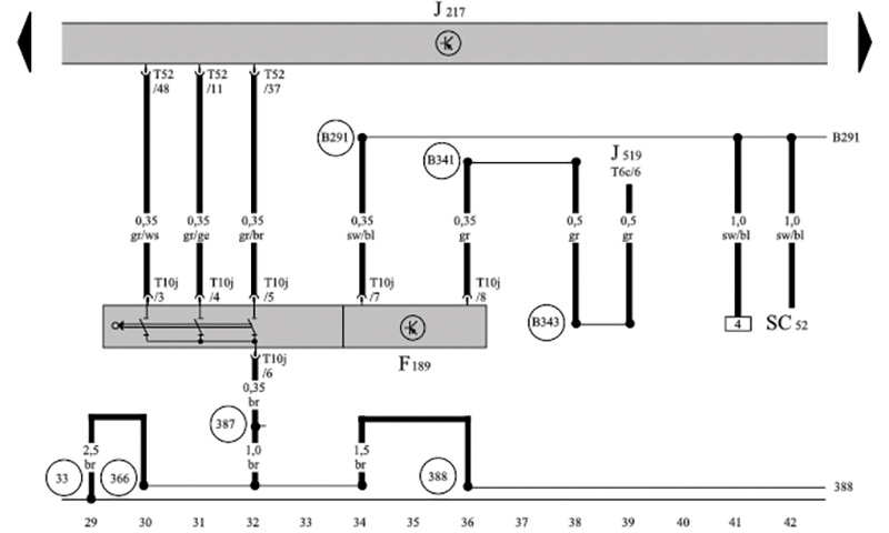
The schematic offers simple information such as:
- SC52 is battery power
- Pin T10j/6 is the ground connection
- J519 is commonly referred to as Central Electrics
- T52/48, T52/11 and T52/37 are the inputs to J217, the TCM
- Input data with VCDS indicates the TCM can recognize F189 as operational
- No faults were found at J159 Central Electrics
- F189 inputs are magnetic (non-contact)
Since there were no power or ground interruptions and F189 seemed to operate “with a mind of its own,†the decision was made to replace F189 after repeating its faults.
It would appear the TCM recognized unintended Tiptronic Mode and downshifted with no driver intent.
Is there another control that can institute an abrupt downshift?
How about F125?
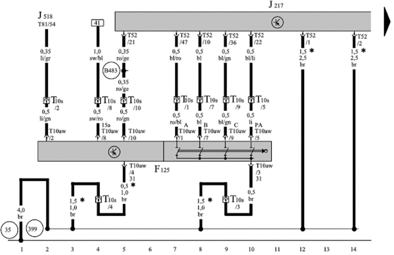
F125 is mounted to the side of the transmission and operated via shift lever cable. Along with the cable, it also operates the manual valve within the valve body.
The TCM recorded no F125 faults or shift solenoid faults.
F125 inputs are mechanical contacts.
Warning: Refer to repair information to correctly remove the entire shifter assembly and printed circuit board. Assemble in reverse order and pay close attention to shifter assembly.
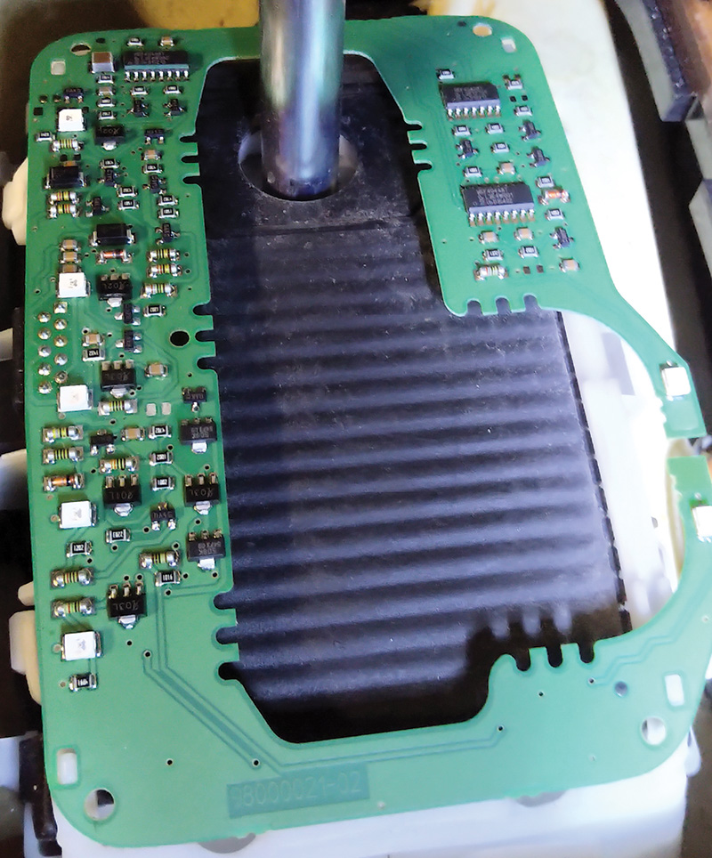
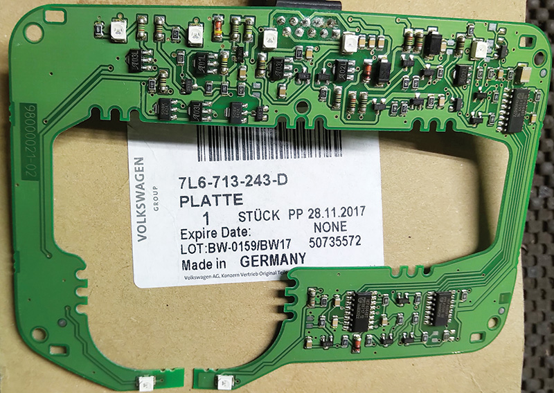
The “Circuit board F189†image is of the NEW circuit board in place and, with it removed, the rubber sliding cover should be inspected and cleaned.
Be very careful unclipping the remaining covers attached to the shifter housing assembly. Use trim tools and hooks to gently lift the plastic latches. Ambient/warm temperature rather than cold temperature is preferred with any interior work.
Pay particular attention to the magnets. The magnets should be firmly in place, clean, with no debris attached to the entire assembly. There should be no tearing of the rubber cover and it should be free to move. That warning will also include the plastic inserts wrapped around the shifter lever for Tiptronic Mode.
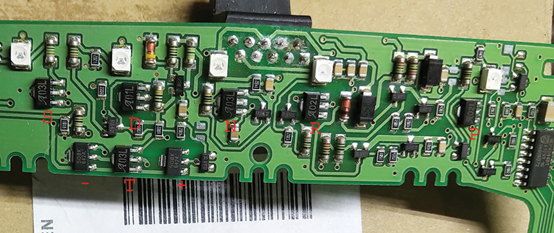
From right to left Park – Reverse – Neutral – Drive – Sport (Magnetic sensors)
The white cubes indicate the LED display.
Notice the oxidized soldering points near the top center section. With a magnifying glass, it was evident something may have been spilled onto the board OR, and we have seen this before, a chemically strong interior cleaning solution.
At the time of a parts request, the answer was “There are six in stock at the warehouse.â€
The replacement was the cure — no faults returned, and no abrupt shifts were evident.
As with any ECM and TCM fault(s), always return to Basic Settings 060 and 063 at the ECM to ensure that throttle and shift point responses are set to factory defaults.
Selector Lever Handle R&R
Note:
- There are four recesses in the handle “arrows†for securing the insert. These recesses were changed. When installing the handle, use the correct procedure for installing the insert.
- Only handles with the modified recesses are delivered as replacement parts. The insert remains the same.
Removing
Note:
This procedure applies to all handles.
To ensure the handle is not damaged adhere to this sequence:
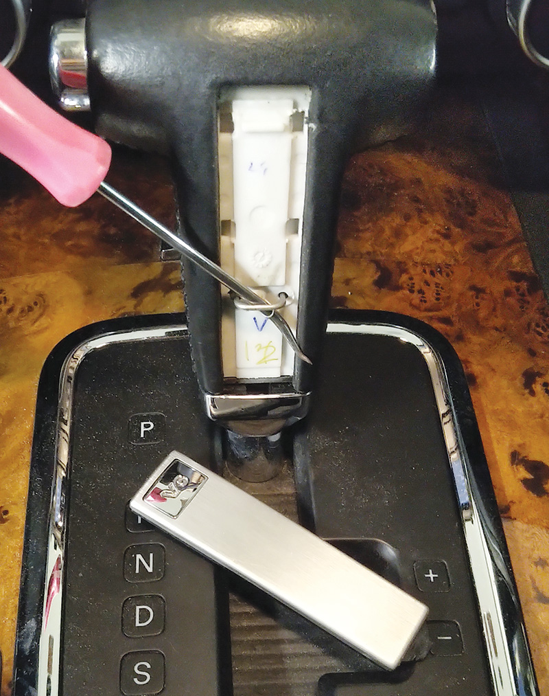
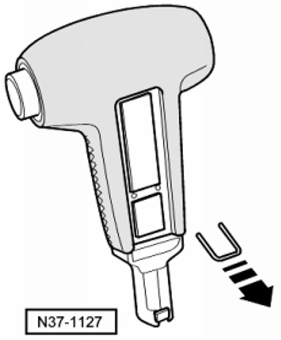
- Pry out the insert.
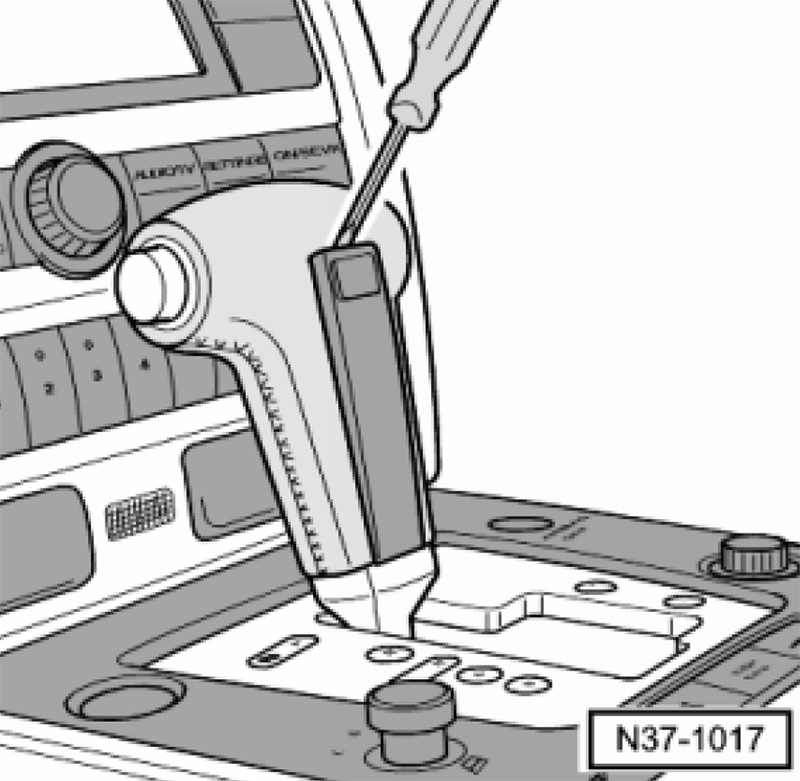
- Remove the retainer from the handle.
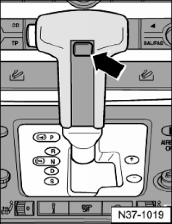
- Pull the button past the pressure point until it is locked in position.
- Remove the handle from the selector lever.
Installing
Note:
Note that there are different procedures for installing the insert.
If the button is inadvertently pressed into the handle, hold the handle vertically and at the bottom. Carefully blow the button outwards again using compressed air until it can be pulled out past the pressure point by hand.
- Reinstall the assembly aid <A> (included with the new handle).
- Push in retainer.
Handle with old recesses
- Press the insert into the handle until it stops.
Note:
To make sure that the tabs on the insert are seated correctly in the recesses on the handle:
- Move the insert approximately 1 mm back and forth in the handle by hand.
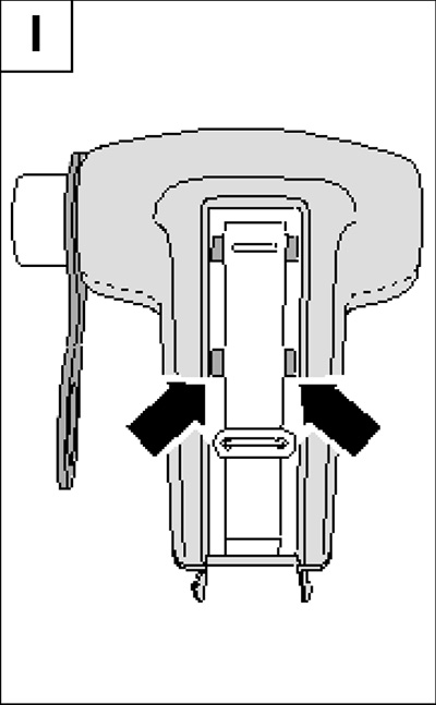
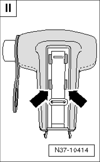
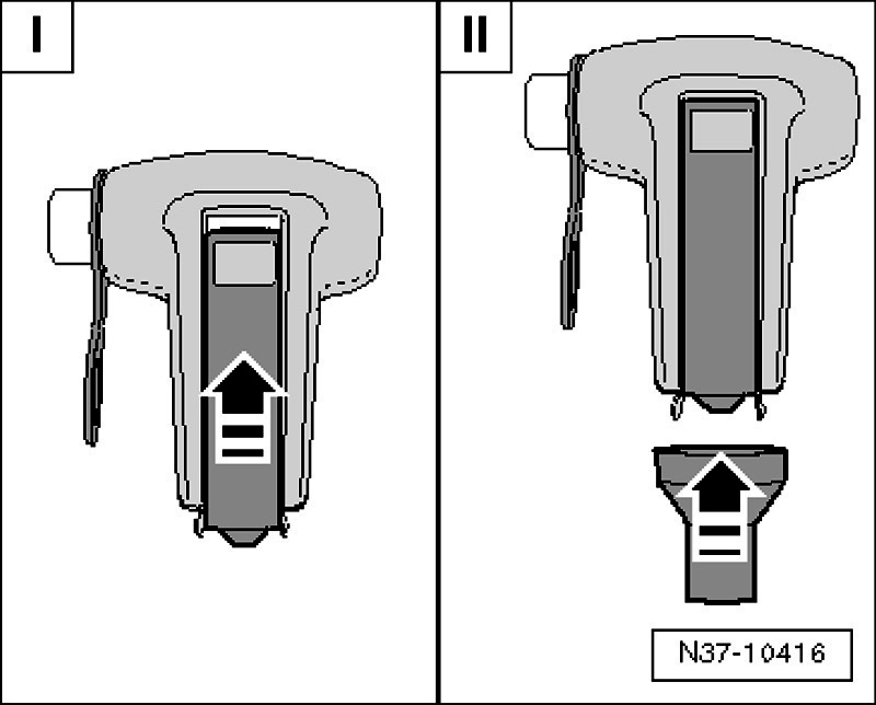
Handle with modified recesses
- Install the retainer <2>.
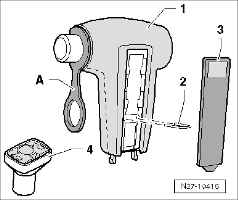
- I – Press the insert into the handle until it stops then slide it upward <arrow>.
- II – Place the sleeve on the handle.
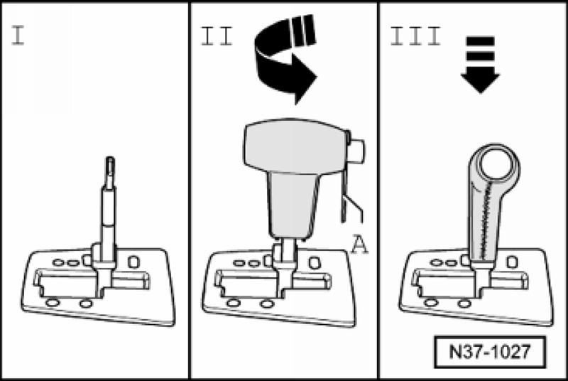
Continuation for all
- Place the selector lever in the N position.
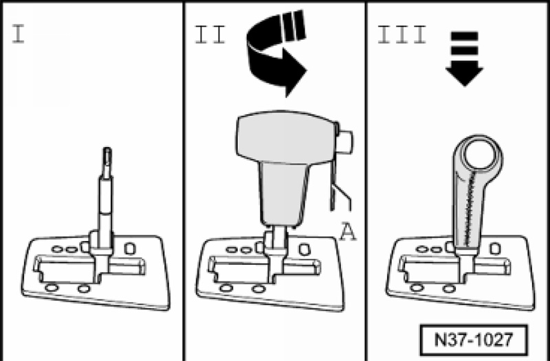
- I – Guide the sleeve carefully through the cover strip/frame and the cross slide lying underneath.
Guide the sleeve carefully through the cover strip/frame when inserting. If carelessly pushing the sleeve in, the cover strip will break.
- II – Install the handle lengthwise until seated, then turn.
Installed position: button facing driver.
- III – Press the handle on the selector lever until it is seated and engages noticeably.
- Remove the assembly aid <A>, operate the button, and remove the sleeve upward.
- Remove the protective foil from the insert and affix the emblem <arrow>.


Hi
I have changed F189 and still having the same error. PRNDS ligthing for all when it touches D.
Please assist
Alexandre