

The electrical systems on today’s vehicles are extremely important. With multiple networks connecting a wide range of electronic control modules, their reliance on a well-functioning electrical system is crucial.
The battery is the foundation of a sound system and should receive periodic state of health checks. Additionally, since the alternator takes energy to turn, Nissan uses a variable voltage control system in order to intelligently manage the load the alternator applies to the engine.
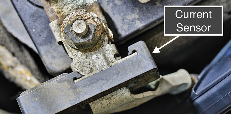
Engine efficiency is a top priority and whenever the engine management system determines that the electrical load on the system is low, this condition may result in lower battery voltage than what you have been accustomed to seeing. A current sensing device has been deployed for monitoring electrical loads placed on the system. This sensor is typically located on the battery negative cable between the battery post and the cables attaching the engine and body.
If you are troubleshooting an electrical system issue and see that additional cables have been attached directly to the battery negative cable, you should know that the electrical loads traveling through these cables are un-measured and will present problems for the variable voltage control system since it cannot accurately measure these loads. These cables should be terminated properly at a body ground so that the systems they support can be properly measured by the variable voltage control system.
The basics —
Battery
As mentioned earlier, the battery is the first item that should be inspected and validated for proper performance before attempting to troubleshoot other systems. If a deficient battery is present, your testing results could be mixed.
Cables and connections
Inspecting for corrosion around the battery cables and connections should always be performed during the course of general vehicle maintenance. Also, one should check for add-on components that may have been improperly installed, such as items attached to the negative battery cable which bypasses the electrical load sensor. Testing the voltage drops on both the positive and negative circuits of the alternator circuit will be covered later in this article.
Battery current sensor
The battery current sensor is located on the battery negative terminal. Its job is to provide two data inputs to the ECM in order for it to be able to intelligently judge the electrical loads applied to the battery at any given time.
One input comes from the battery temperature sensor. This input is provided by a Negative Coefficient Thermistor (NCT) residing inside the current sensor. The other data signal is the actual amperage flowing through the battery negative cable. This input is supplied through a hall-effect device that works similarly to a current probe that one would use with their digital volt/ohmmeter or oscilloscope.
Our subject vehicle is a 2014 Juke and its current sensor has a total of four wires. The terminals and circuits are as follows:
- Pin 1: power supply – shared with the G-sensor (vehicle dynamics accelerometer) located under the driver’s seat.
- Pin 2: battery temperature sensor. With an NCT voltage goes down as battery temp increases.
- Pin 3: ground (shared with the G-sensor and the fuel level sensor).
- Pin 4: current sensor output signal.
Troubleshooting this sensor is pretty straightforward and should always begin with a check for DTCs followed by checking for the proper power and ground supplies and signal output.
Alternator
The alternator is in place to supplement the loads, or electrical energy, consumed by the vehicle from the battery. During times of high electrical loads, such as when the air conditioning system is engaged, the cooling fans, lights etc. are on, the alternator will receive commands from the Integrated Power Distribution Module (IPDM) to change the level of energy transmitted back to the battery.
Later in this article we’ll cover the signal commands and how to look at these with a volt meter or scope. It should be noted that the alternator’s job is NOT to recharge a discharged battery. If the alternator is frequently placed in this mode, then the life of the alternator alternator can be shortened.
Diagnostics
When addressing a charging system complaint or symptom, again, the battery is the first item on the list to be addressed. Accurate test results cannot be achieved with an impaired battery. Testing the performance of the alternator should be gauged against its rated specifications. The following references were sourced from service information on our 2014 Juke:
- Nominal output: 110 amps at 12.0 volts
- Normal voltage regulation control range: 11.4 – 15.6
- Minimum rpm with no load and 13.5 volts applied: less than 1,300
- Hot current ratings: 95 amps at 2,500 rpm and 116 at 5,000 rpm
NOTE: rpm figures are for the alternator, not the engine speed.
Voltage drops
Voltage drop testing is used for checking the integrity of cabling tasked with carrying electrical loads. Here, we’ll be discussing how to go about testing the power and ground circuits supporting the high current produced by the alternator.
Voltage drop can be determined by measuring the voltage consumed by the circuit while flowing nominal current. It cannot be measured accurately without the proper amount of current flow or load. Therefore, if you have a vehicle that isn’t able to generate any energy due to an internal failure, you’ll be unable to test the voltage drop on the power and ground circuits in a normal manner. However, with a good battery and enough access, one could utilize a volt-amp tester that has a carbon pile load component to validate the circuits.
The problem, however, is that most modern powertrains are extremely compact where access to the main B+ terminal on the alternator can be a challenge. However, if you are able to gain access and want to test the voltage drop in the cable, here’s how you can set up the test:
- Connect the red cable from your VAT to B+ at the alternator
- Connect the black cable from your VAT to the B- post at the battery
- Connect the amp probe from your VAT around either of two cables previously connected
- Connect the red lead from your DVOM to the B+ post at the battery
- Connect the black lead from your DVOM to the B+ post at the alternator
- With the DVOM set to measure voltage, slowly rotate the carbon pile load knob clockwise until you reach 40 amps while observing the voltmeter. No more than 0.50 volts should be observed.
The ground side of the circuit can be tested similarly.
- Connect the red cable from your VAT to B+ at the battery
- Connect the black cable from your VAT to the case of the alternator
- Connect the amp probe from your VAT around either of two cables previously connected
- Connect the red lead from your DVOM to the B- post at the battery
- Connect the black lead from your DVOM to the alternator case
- With the DVOM set to measure voltage, slowly rotate the carbon pile load knob clockwise until you reach 40 amps while observing the voltmeter. No more than 0.25 volts should be observed.
If the alternator is able to output nominal current, testing the voltage drop on the alternator can be accomplished by making the voltage measurement connections listed above while the engine is running and the alternator is being commanded to output nominal energy. You can achieve this by turning on various loads, using the VAT carbon pile to apply a load, or by using CONSULT III Plus.
When applying vehicle loads, ideally, you’ll want to make sure you apply enough load that would require that the alternator output at least 40 amps. This is so we can make the same voltage drop measurements outlined in the carbon pile tests described above. This also means that we should be using a current probe to verify that this current is actually at this level.
If you are using the VAT to apply the load, please remember that your negative cable should be connected on a good body/engine ground post to that the load will be properly measured by the current sensor mounted on the negative cable. Using CONSULT III Plus, a bi-directional control function is sometimes available which can be used to command the alternator. This will be discussed later.
Regulation
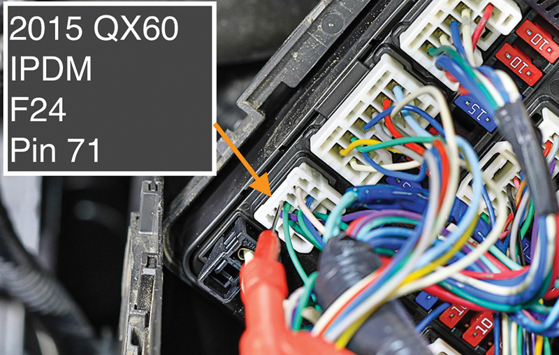
As mentioned earlier, the alternator is controlled by the ECM via the IPDM. Testing the control circuit can usually be accomplished by accessing the IPDM and studying a wiring schematic. Once the appropriate circuit has been identified, an appropriate back probe pin can be carefully inserted down the back side of the connector in order to sample the command signal.
Consult III Plus
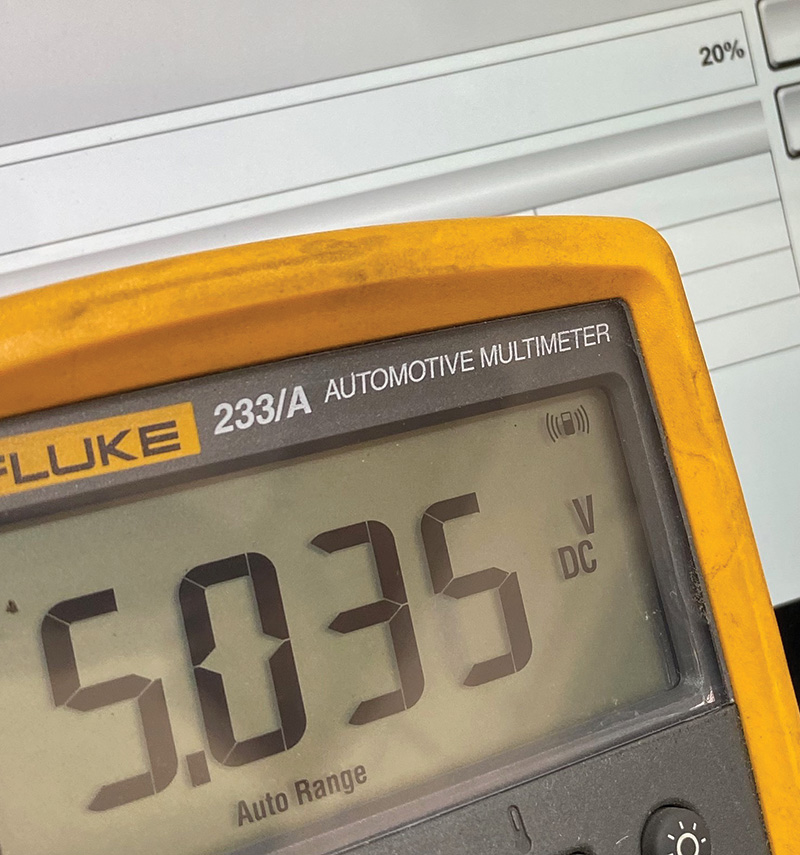
With some vehicle applications, you can control the alternator via the scan tool. Enter ENGINE -> Active Test -> Alternator Duty.
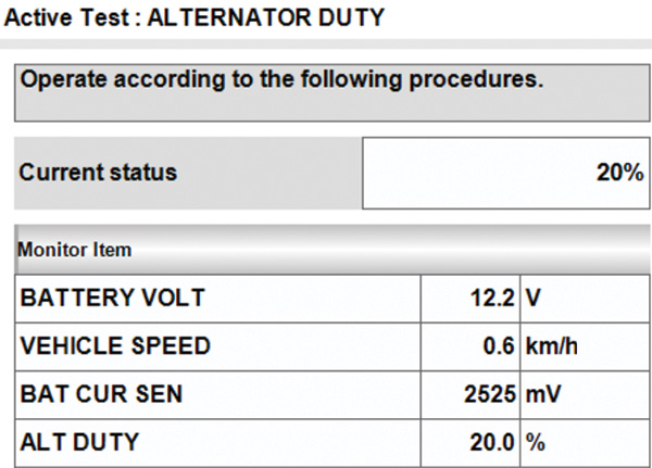
After locating the alternator control pin at the IPDM, you can connect your scope or volt meter and monitor the raw output command. With minimal loads applied to the battery, the control command should be approximately 6.3 volts. The IPDM will pull this voltage down anywhere from 10 percent to 90 percent. You can see that with a 20 percent load the system voltage was at 12.1 volts. This command is essentially turning the alternator off. With a 20 percent command, the IPDM measured 5.03 volts.
Moving the CONSULT III Plus to 50 percent yielded 13.5 volts on the system and 3.08 volts measured on the command circuit.
At 90 percent command the system voltage rose to 15.2 volts with the command signal riding at 0.549 volts.
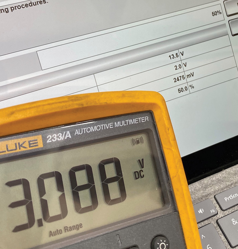

It should be noted that with the known baseline command from the IPDM on our test vehicle running at 6.3 volts, one should be able to take that number and subtract out the percentage being commanded during the active test and arrive at an approximately expected voltage. If you take the three stages above and do the math, you’ll see those numbers somewhat line up in the table below:
| IPDM Command | Measured Volts | Multiplier | Calculated |
| 20 percent | 5.03 | .8 | 5.04 v |
| 50 percent | 3.08 | .5 | 3.15 v |
| 90 percent | 0.55 | .10 | 0.63 v |
Carbon pile testing
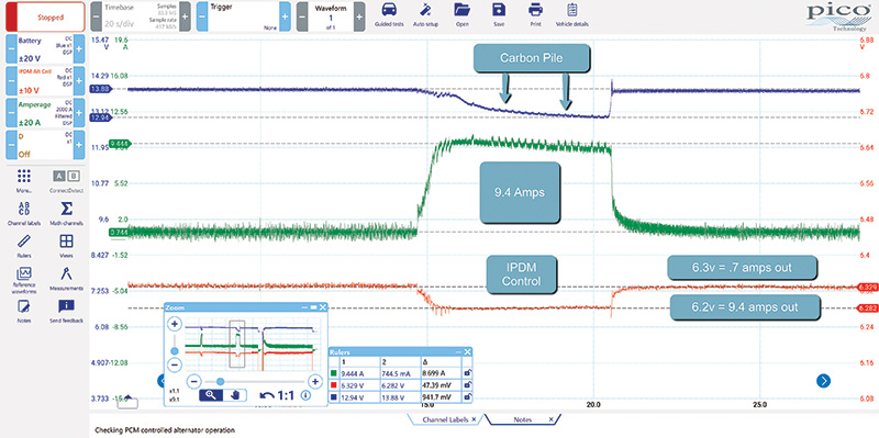
As mentioned earlier, if you’re going to use a carbon pile to exercise the alternator, you’ll want to make sure that you place your negative test cable on the engine block, or you’ll end up with an incorrect conclusion. This is done so that the current sensor will be able to react accordingly. The image on the next page shows what happens when the negative VAT cable is placed on the negative battery terminal resulting in an inaccurate test.
The top trace (blue) from the scope is battery voltage as measured at the battery terminals. The middle trace (green) is from the scope’s current probe connected around the negative cable. The bottom trace (red) is the control signal out from the IPDM to the alternator. When the load was applied to the battery, the IPDM signal voltage changed from 6.3 volts to 6.2 volts, resulting in an additional current of 9.4 amps from the alternator. This is not what one would expect when applying a load that took the battery voltage from 13.8 to 12.9 volts.
Conclusion
The alternator plays an important role in ensuring that the vehicle’s numerous systems operate properly. When trouble surfaces, there are several tools one can leverage in order to test system performance and accurately diagnose faults.


0 Comments