
Classic owners are passionate about their cars, and many can’t live without their cruise control. Here’s how to keep the Mercedes-Benz E-Tempomat system traveling down the road.
While most of your shop’s daily work is probably on newer Mercedes-Benz models, there are many customers with classic models, and their cars still need regular service and maintenance. With that in mind, StarTuned plans to deliver a series of occasional articles on some of the classic systems used in these older models. Today, we will explore the E-Tempomat cruise control system used in vehicles from the mid-1980s until the early 1990s.
The E-Tempomat cruise control system we’ll focus on is installed in later-productioon S-Class model 126 vehicles, but the same basic system was also installed in the SL (107), E-Class (124) and 190-series (201) models. You can tell if it’s an E-Tempomat system by the components: The throttle is actuated by an electric motor, and the cruise control amplifier has 14 pins. Earlier cruise control systems used pneumatic throttle actuation and a 10-pin amplifier, while later systems used the Electronic Accelerator system which is a part of the traction control system.
The system works by measuring vehicle speed and actuating the throttle linkage to increase or decrease engine output. Many customers love their cruise control, using it as an easy way to control vehicle speed, reducing both fuel consumption and the possibility of a speeding ticket. Not just for long highway cruises, even the daily commute is made easier, allowing the driver to focus on tasks other than speed control, which research shows also helps make for safer driving by reducing critical workload.
The Driver’s View
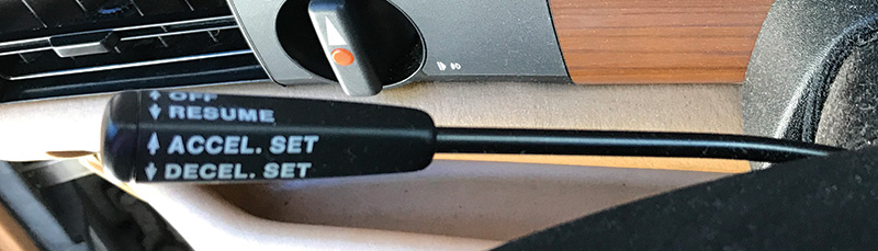
Mercedes-Benz uses a unique lever mounted on the steering column to control the system. Tipping the 4-way lever upwards sets the desired speed, or increases the set speed by a small increment. Tipping the lever down also sets the speed, or decreases the set speed by a small amount. Exactly how much the speed is increased or decreased depends on the E-Tempomat version, but it is generally either about 1 MPH or 1 km/h. Holding the lever either up or down increases or decreases the vehicle speed at a set rate, although on a downhill slope the speed may not decrease as quickly. Pulling the lever towards the driver resumes a previously-set speed, while pushing the lever away from the driver switches the system off. Other ways to switch the system off include tapping the brakes, pressing the clutch pedal (in manual-transmission vehicles), or if the system detects an unreasonable deceleration (about 1.5 m/s2). The system cannot be activated below about 40 km/h (25 MPH).
If the driver overrides the set speed by pressing the accelerator, for example when passing, upon releasing the pedal the vehicle will coast down and resume the set speed. It is important to avoid shifting into neutral in an automatic transmission vehicle, as this will cause the engine to rev up to the over-rev limiter setting. The set speed is erased when the ignition is switched off.
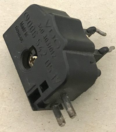
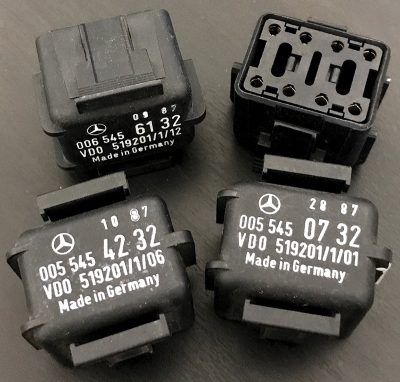
Originally, the E-Tempomat control amplifier was a purely analog circuit, with a different part number for each vehicle. The plastic connector end was coded by color, and the part number is stamped on the housing. Since vehicles have different power-to-weight ratios, a different reaction by the amplifier is needed – for example, a 190D 2.2 needs to approach the throttle more aggressively when the speed drops, while the same reaction in a 560SL might be a little scary. Later versions, including the replacements available today, were digitally controlled, and a coding plug was attached to the amplifier to set the specific throttle response and other parameters.
Components
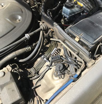
The system consists of only four components: The amplifier (or control unit), the actuator motor, the speed sensor and the control switch. There are also several other related components, like the throttle linkage, that can be relevant in a diagnosis. Let’s look at these components in detail.
As mentioned previously, the control switch is a 4-position switch. Looking at the wiring diagram for a 1988 560SEL, we see that each of the three switches – one for up/down motion and two for forward/backward motion – have two actuated positions and an ‘at rest’ position. With Pin 2 on the switch connector as the common for all switches, accelerate/set has continuity to Pin 4, and decelerate/set has continuity to Pin 3, when the switch lever is actuated appropriately. For the resume function, continuity is to pin 5 when actuated. Pin 1 has continuity in both the resume and resting positions, and loses continuity in the off position.
Using your ohmmeter, you can verify that all the switches are switching when they are supposed to, and by actuating them several times (including with more and less force) you can check for intermittent contacts. Because the switch’s connector contacts (down in the steering column) can also contribute to the problem, you might consider also measuring the switch values directly at the amplifier plug.
The speed sensor is very simple. In a 126 the electronic speedometer has a connection on the back that sends out pulses that correspond to vehicle speed. Compare that to the 124 or 201, which have a speedometer cable running from the transmission to the back of the mechanical speedometer: There is an inductive sensor on the back of the speedometer that sends out the pulses. The pulses vary in frequency depending on the vehicle, but a couple of pulses per (rear) wheel revolution should be expected. Although an oscilloscope would be ideal to monitor these pulses, your voltmeter will do just fine. Just note that the rear wheels need to be spinning a couple of revolutions per second to get a good reading. The inductive sensor is no longer available; a Hall-effect version must be retrofitted as a replacement.
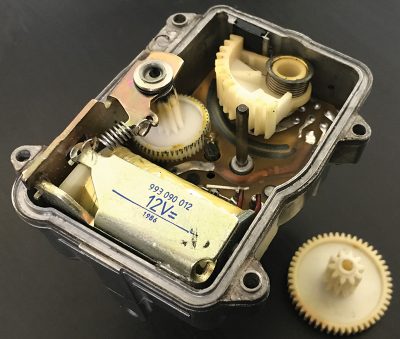
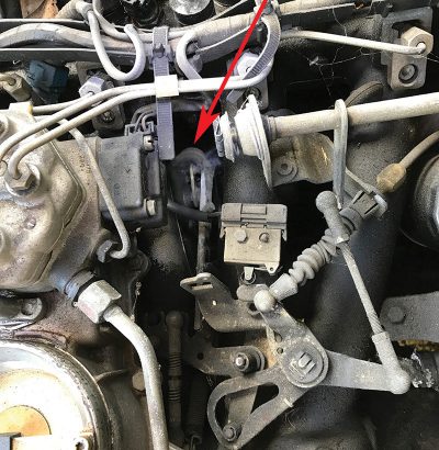
The actuator, on the other hand, is not so simple. It contains a motor to move the throttle, a two-track variable resistor to track the position of the output lever, and a clutch to engage or disengage the motor from the output lever. Testing is possible with a Mercedes-Benz special tool, W126 589 05 21 00. However, many of the symptoms will clearly indicate if the actuator itself needs to be replaced, and we’ll look at some diagnosis steps we can take in a moment. In any case, avoid opening the actuator, as might never work right again. There is a security pin on the actuator housing, which must be broken to open it. The image here is just to satisfy your curiosity.
The cruise control amplifier, as an electronic control unit, cannot be tested directly, but we can easily say that if all of the inputs and outputs to the unit are correct, either the system is operating correctly or the amplifier needs to be replaced. The unit only has 14 pins, so it is fairly quick and easy to check every one of them and come to a conclusion. We’ll get into the details when we talk about diagnosis.
Other Related Systems
One of the most important of the related systems is the brake light circuit. Power is fed to the brake light switch, which is on the brake pedal lever, and when the brake pedal is pressed, the switch closes and powers the brake lights. The E-Tempomat system detects this and disengages the system in two ways: The amplifier is switched off and the actuator clutch is disengaged.
Pin 8 of the cruise control amplifier is the “Disengage†circuit, and needs to sense a ground to allow the amplifier to function. It gets this ground thorough the cold filament of the brake light bulbs. In a 1988 560SEL, for example, the output of the brake light switch connects to junction point X21/2 (behind the instrument cluster), which delivers power to the brake light bulbs after passing through the exterior lamp failure monitoring unit N7. If all brake light bulbs are burned out or disconnected, the lack of a ground through the bulb filaments will prevent the system from engaging.
In a similar way, the clutch inside the throttle actuator gets power from the amplifier, but relies upon the same brake light circuit ground (through the cold bulb filaments) to operate, so if the ground is removed (by switching the brake lights on) the actuator clutch disengages instantly. Also note that other systems, notably ABS and the Anti-Theft Alarm, also connect to the brake light circuit, but rarely cause problems with cruise control.
Both the brake light switch and the cruise control system get power from Fuse 9, so a fuse failure ensures the system cannot operate. The system ground (at W1) is connected to amplifier Pin 12 and (originally in production) Pin 14. Note that in vehicles where Pin 14 is connected to ground, the new digital amplifier won’t work. At the time, there was a Dealer Technical Bulletin explaining the issue, but that document is no longer available. The solution is to remove Pin 14 completely, leaving that connector hole empty.
An mentioned, vehicle speed is a series of pulses, with increasing frequency indicating increasing speed. In Mercedes-Benz vehicles with a mechanical speedometer cable, there is a sensor on the back of the speedometer that generates these pulses, while in electronic speedometer models the speedo re-forms the pulses received from the inductive sensor at the transmission output shaft. In either case, the speed signal is received by the cruise control amplifier on Pin 11. Since several other systems use the vehicle speed signal – CIS-E engine control, fuel pump relay, air conditioning and radio to name a few – there will be other systems affected if the vehicle speed signal is faulty.
Diagnosis
As mentioned previously, the actuation switch has four inputs to the amplifier, on Pins 2, 3, 4 and 6. The connections to the actuator are on Pins 5, 7, 9, 10 and 13. Pin 5 is the actuator clutch power output mentioned before, while Pins 7 and 10 control the actuator motor. The voltage on these two pins varies both in magnitude and polarity, since the DC motor used to actuate the throttle needs to be able to run in both directions and at variable speed. Pins 9 and 13 are the throttle-position sensor power source and returned position voltage, respectively. The position sensor, which is a high-reliability potentiometer, is grounded at W1 along with the amplifier.
That covers all 14 pins of the amplifier, and diagnosis is as simple as taking 14 readings (and 2 of them are grounds!). But as we mentioned, there are other components related to this system which may need to be checked as well.
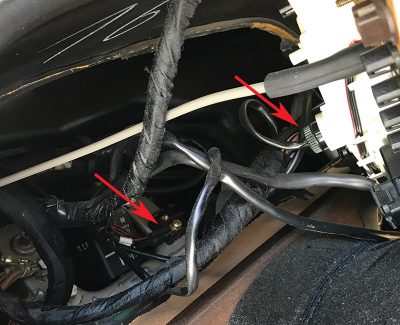
One frequently-heard complaint is a ticking or clicking sound coming from the actuator, along with the complaint that cruise control is inoperative. This is a symptom of a problem with the feedback potentiometer, where the amplifier believes (inaccurately) the throttle position is too high, causing the amplifier to run the actuator motor in an attempt to bring the throttle linkage to idle position. The clicking is the ratchet in the actuator clutch, since the actuator motor is also disengaged in this situation. This symptom is often caused by a poor ground to the actuator at Pin 1 of the actuator connector, located in the engine compartment.
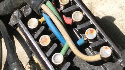
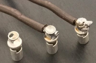
Because of the position of Pin 1 in the connector, and the silver-plated brass material originally used for the female electrical contact, this contact can become slightly enlarged and allow the ground to be lost. When this happens, the sensor floats at the supply voltage, which would be an (incorrect) indication of full throttle. This may happen only intermittently, particularly after the engine compartment gets hot. The solution is the replace the female contact with an improved version (the only type available today) made of Beryllium-copper, which does not become malformed easily. Simply solder in all new female contacts using the latest version (A003 545 26 26).
Another complaint we’ve heard is that the cruise control system operates more-or less fine, but tends to ‘hunt’, or constantly change throttle position from a little too much to a little too little, almost continuously while in operation. Found especially in higher-mileage vehicles, this is a clear symptom of a worn feedback potentiometer in the actuator. What happens is that the potentiometer resistance surface eventually wears out in just one small spot, and the only solution is a new actuator.
This symptom can also be caused by a sticking throttle linkage. Clean and lubricate, and verify the correct adjustment as explained in STAR TekInfo in the Legacy Microfiche: The topic of Cruise Control is found in Volume 2. Scroll to the bottom to find cruise control info for your particular model. Download and open this PDF conversion of the microfiche and check the index (at the end of the document) for the adjustment procedure applying to your specific model and year.
In some models, a mild hunting while traveling downhill can be caused by the deceleration fuel shutoff system. With fuel shut off, the engine braking can be enough to slow the car enough to need some throttle. This resumption of fuel injection can be felt by sensitive drivers. The Legacy Microfiche (in STAR TekInfo as explained above) explains in topic 30-576 how to install a relay and harness to address this complaint.
In the digital cruise control amplifier, Mercedes-Benz decided to use a so-called Reference Resistor to set the characteristics of the amplifier, allowing a single part number amplifier to be used in several different models. When replacing an analog-type amplifier, be sure to also order the correct reference resistor or the system won’t work. If you are replacing a digital amplifier, you should swap the reference resistor over to the new amplifier. Test values can be found in the legacy microfiche as explained above.
So now we know how this relatively simple system operates, from both the customer’s view and as a system. We have looked at each of the four major components and a few related systems and learned how they function and how they can be tested. We also became aware of a few Service Information bulletins with useful information for this convenience system. And finally we learned about a few of the more common complaints, learned their likely causes and how to correct them.
Again, while these older models probably don’t make up the bulk of your customer base, we all know just how enthusiastic and passionate these classic-model owners can be. Your efforts at keeping their “baby†operating as designed will be appreciated by your customers, and likely profitable for you. Now you know everything you need to know about the Mercedes-Benz E-Tempomat cruise control system to keep the cruise control system, and your customers, happy.


0 Comments