
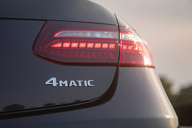
Introduced over three decades ago, this feature has gone through several generations. Do you understand how to handle them all?
In the 1980s the automotive industry saw the beginning of a huge surge in the demand, research and development of automobiles and SUVs that could provide better traction, slip control and all around safety in various driving conditions. 4WD signified a lifestyle that could take the owner almost anywhere, even though soccer moms were destined to drive them in the world of concrete and freeways, shopping centers and big box stores. These were labeled with various descriptions such as 4 wheel drive, all-wheel drive, and limited slip drive among others. While there is no universally accepted set of terminology that describes the various designs and functions, the terms used by various manufacturers will often reflect marketing rather than significant technical differences or actual engineering considerations between systems. There is an international standard J1952 that recommends only the term “all-wheel drive†with additional sub classifications that cover all types of AWD/4WD/4×4 systems found on production vehicles.
Early 80s production 4-wheel drive systems had their issues however. Germany’s Auto Motor und Sport, a serious automotive magazine, carried out comparative tests on the early Audi Quattro that showed that its four-wheel drive gave no advantage in terms of road-holding on wet, dry, or snow-covered surfaces and virtually no protection against hydroplaning or loss of control on black ice, and no reduction in braking distances. But four-wheel drive did improve grip – the ability to move away from rest and accelerate – quite substantially, because the engine’s torque is split into four smaller units rather than two big ones and is fed through four tires rather than just two. The advantage is most noticeable on snow or wet surfaces, and even more so with a powerful engine. Since antilock braking characteristics had not yet been put into production vehicles, this again turned in to a huge disadvantage when descending a snow-covered slope – exactly the occasion many people saw as the justification for purchase of a four-wheel drive car. Also, this is one reason why Mercedes-Benz waited until they had it right before introducing 4MATIC.
Long before the eighties Mercedes-Benz was at work developing and refining 4-wheel or all-wheel drive. Paul Daimler, the son of the company’s founder, came up with the first designs featuring all-wheel drive possibly as early as 1903. In 1907, the “Dernburg-Wagen,†as it was known, was produced for driving in Africa. Although built on the basis of a truck, it was designed as a passenger car, making it the forefather of today’s cars with 4MATIC drive. The first ever all-wheel drive passenger car from Mercedes-Benz was the W124 E-Class model series, whose 4MATIC versions made their debut in 1985 at the IAA International Motor Show in Frankfurt. The 4MATIC system entered production in the W124 model series in 1987.
This first generation 4MATIC system was originally an electronically controlled system with automatically engaging four-wheel drive. The system employed locking central and rear differentials to provide additional traction in slippery conditions. The center differential, actually a transfer case, contains two clutches. Each hydraulically enabled clutch is controlled separately to allow for three modes of operation: Conventional two-wheel drive, where the rear wheels receive 100% of engine torque; four-wheel drive with either a 50:50 torque split; or a 35:65 torque split front/rear.
The rear differential lock introduced the automatic locking differential system ASD, which can engage to help fight rear wheel slip. Due to safety and stability concerns there is no front differential lock.
4MATIC uses wheel speed inputs from the Anti-lock Braking System ABS, along with a steering wheel angle sensor, to decide when to engage. 4MATIC is disengaged automatically if the service brakes are applied.
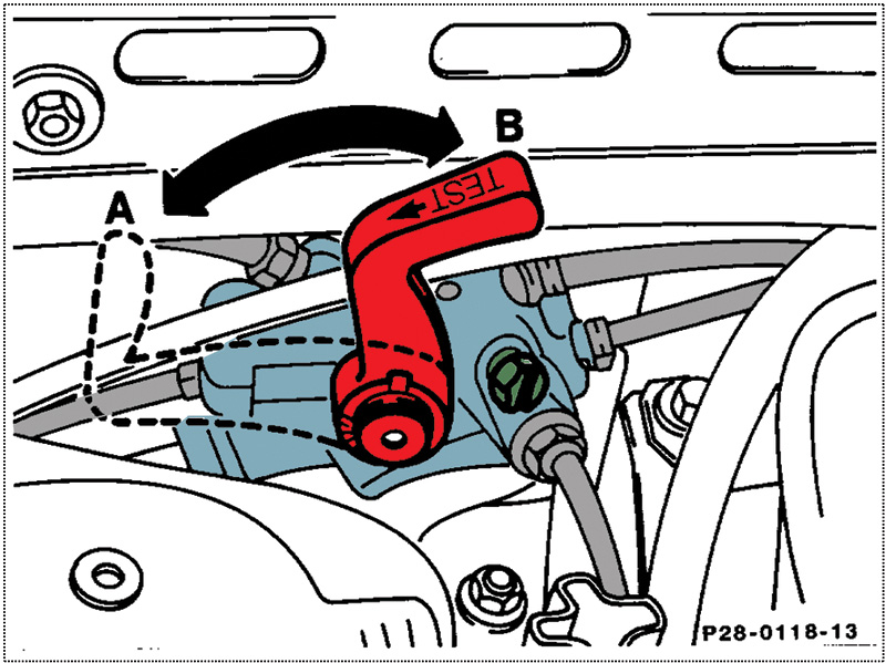
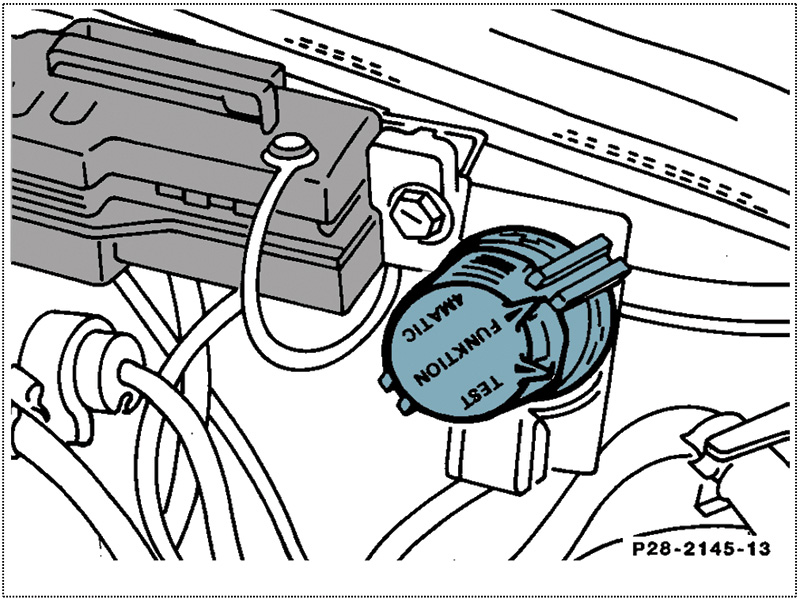
Two model 124 (E-Class) variants of the first-generation 4MATIC system were produced: the first system (from start of production until approximately April 1991) used a mechanical lever (red, above right front wheel well) to disconnect the system hydraulics, while the second system variant use an electrical switch (near the X11/4 diagnostic connector near the battery) to remove power from the system. In test mode, the later variant allows the self-leveling system to continue operation. In 1993, the multi-plate clutch transfer case was discontinued.
Second Generation
4MATIC was reintroduced with the 210 (E-Class) in model year 1997 as a second-generation system. The new 4MATIC was now a full time all-wheel drive system with a single-stage transfer case providing a front-rear torque split of 35:65. Traction control is achieved using the Electronic Traction System (ETS), which employs the ABS system (with additional valves) to monitor and then partially brake any wheel which loses traction, simulating a limited-slip differential. This much simpler system, removing the need for a multi-disk clutch in the differential, is also featured in the M-Class SUV.
Third Generation
Since 2008, some versions of 4MATIC have provided true AWD where the system is permanently active. Sophisticated engine management and ABS systems control the amount of torque transferred to each wheel, allowing the system to be effective at any speed. From March 2008, Mercedes-Benz also began to offer the CL-Class luxury coupe (C 216) with all-wheel drive in the CL 500 4MATIC model. At its heart is the 7G-TRONIC seven-speed automatic transmission, which had been specially developed for all-wheel drive models and has a transfer case with a center differential lock incorporated into it. It splits the drive torque between the front and rear axle in the ratio 45:55. The newly-developed multi-plate clutch at the center differential transmits the engine’s power to all four wheels with a basic locking effect of 50 Newton meters between the front and rear axle. This results in even better start-off characteristics and handling stability on slippery surfaces. At the same time, the all-wheel drive system is exceptionally efficient: the CL 500 4MATIC consumes no more fuel than the corresponding rear-wheel drive model.
Fourth Generation
In model year 2010 MBUSA launched what is now the fourth generation of 4MATIC with the new E-Class (type 212), featured in the E350 and E550 sedans.
In 2016, Mercedes-Benz introduced a new 4WD system called 4MATIC +. This system can send 100 percent of the available engine torque to either the front or rear axles.
In the fifth-generation E-Class an additional setting was introduced in the E63 S AMG model that disconnects the front axle from the powertrain, effectively turning it into a rear wheel drive automobile. This has become known as “Drift Mode.â€
Of course, each 4MATIC generation has several unique characteristics and functions that space doesn’t allow us to describe here. Be sure to check the Mercedes-Benz Workshop Information System (WIS) and other
service literature for all the specifics of the vehicle you’re working on.
Service and Maintenance:
Early Versions:
Maintaining and servicing these early models is fairly straightforward, simply follow the recommended maintenance schedules and intervals. Pay particular attention to the correct fluids and additives called for in transmissions, transfer cases and differentials. The maintenance system sheet for these models call for transmission fluid and filter change at 30k mile intervals. The transfer case and rear differential fluids should have been changed at the initial (1,000 mile) inspection service, after that they are considered “lifetime fill.â€
While Mercedes-Benz engineers surely know what is best for their vehicles, we often hear customers questioning the lifetime fill designation. Indeed, our take (especially in these older vehicles) is that a fluid change can’t hurt, especially when comparing the cost to that of a replacement unit. At the very least, check the cleanliness of the fluid and replace it if soiled.
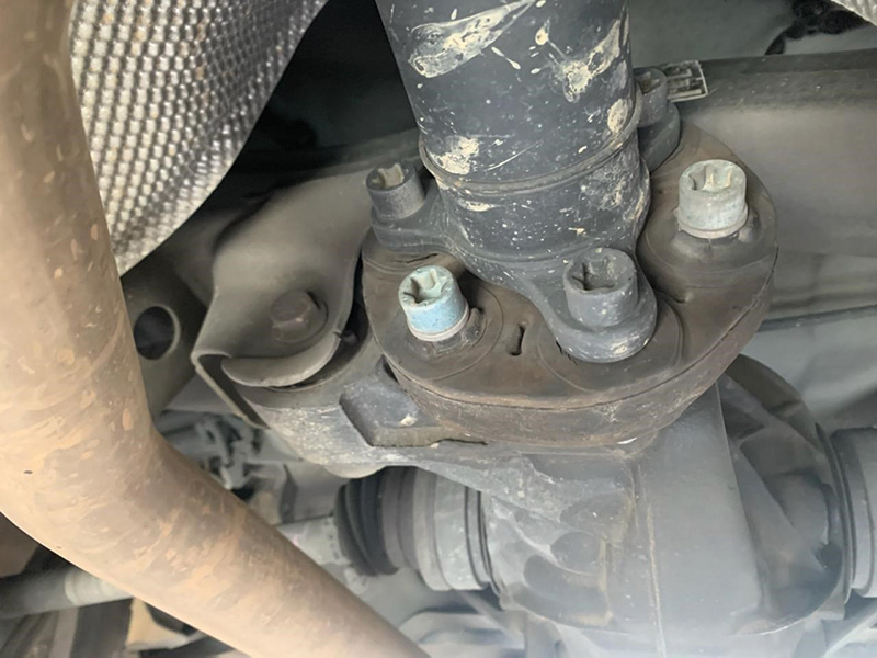
The ASD-equipped rear differential should have an information plate attached. The fluid should be checked at every other lubrication service and changed at the discretion of the technician thereafter. Take into consideration the type of driving and the conditions and be proactive. You’ll not be doing your customer any favors by waiting until the fluid is black and full of shiny particles.
| The modified Specifications for Operating Fluids are available in the table, the corresponding BB documents are in WIS or the BeVo Portal on the internet at: bevo.mercedes-benz.com for viewing. | ||||
| ATF 134 B eVo 236.14 | FE-AFT 134 BeVo 236.15 | ATF D97 B eVo 236.16 | DCT ATF BeVo 236.21 | |
| Oil Color | Red | Blue | Gold | Gold |
| Part Number | A001 989 68 03 | A001 989 78 03 | A 001 989 92 03 | A 001 989 85 03 |
| 5-Speed Automatic Transmission 722.6 | X | |||
| 7-Speed Automatic Transmission 722.9 before production number 23834526 | X | |||
| 7-Speed Automatic Transmission 722.9 after production number 23834526 with engines 113, 152, 156, 157, 275, 279 | X | |||
| 7-Speed Automatic Transmission 722.9 after production number 23834526 without engines 113, 152, 156, 157, 275, 279 | X | X | ||
| 7-Speed Automatic Transmission Hybrid 724.2 | X | |||
| 9-Speed Automatic Transmission 725.0 | X | |||
| 7-Speed Dual-clutch Automatic Transmission 724.0 | X | |||
| Here is a handy chart to identify which type of automatic transmission fluid to use. | ||||
| Passenger car, sheets 235.0 to 235.74 | |||||||||
| Major assembly | SAE grade | Sheet no. 235 | |||||||
| .0 | .3 | .7 | .10 | .15 | .61 | .62 | .74 | ||
| Front axle (4MATIC) | 85W-90, 90 | â—‹ | â— | ||||||
| Rear axle model 163 | â— | ||||||||
| Rear axle model 164 with rear wheel drive (4 X2) | |||||||||
| Rear axle model 251 with rear wheel drive (4 X2) | |||||||||
| Major assembly | SAE grade | Sheet no. 235 | |||||||
| .0 | .3 | .7 | .10 | .15 | .61 | .62 | .74 | ||
| Rear axle model 117, 156, 176, 246 4MATIC (4 X4) | |||||||||
| Rear axle (standard differential) | 75W-85, 85W-90, 90 | â—‹ | â— | ||||||
| Rear axle with AMG differential lock Model 230.479 Model 204.077/277, 211.076/077/276/277, 219.376/377, 230.470/472/474 with code 471/P30 Model 171.473, 203.076/276, 209.377/477 Model 172.475, 231.474/479, 463.270/271/272/273 | 75W-140 | â— | |||||||
| Rear axle with differential lock model 164, 199 | 75W-85 | â— | |||||||
| Major assembly | SAE grade | Sheet no. 235 | |||||||
| .0 | .3 | .7 | .10 | .15 | .61 | .62 | .74 | ||
| Differential with limited slip | 75W-85, 85W-90 | â— | |||||||
| Manual steering | 85W-90, 90 | â— | |||||||
| Manual transmission as of transmission sequence number 7 340 241 (717.4 and 716.6) | 75W-80W | â— | |||||||
| Major assembly | SAE grade | Sheet no. 235 | |||||||
| .0 | .3 | .7 | .10 | .15 | .61 | .62 | .74 | ||
| Manual transmission SG 150/180 (716.5) | 75W-80W | â— | |||||||
| Manual transmission NMT 270, 370/400 | â— | ||||||||
| Manual transmission 700.7 (Citan) | â— | ||||||||
| Consult the proper maintenance chart for your specific model, this is for an early version. Also available online, simply search for “MB Bevo,†the Mercedes-Benz service fluids website. | |||||||||
As these models will undoubtedly have plenty of miles on them, some particular issues may arise. One is addressed in a XENTRY TIPS document LI28.00-P-060078, which references a noise in the drivetrain and diagnosis. The complaint is a humming, howling, or droning noise from drivetrain which is caused by overlaid vibrations excited by the engine, suspension and drive train.
First, address the front engine mounts:
- Visually inspect the positions of the front engine mounts. They must be correctly seated in the engine support. (Obviously be sure they are not worn out!).
- Unscrew the engine mount bolts. The thread in the engine mount must line up with the hole in the integral carrier.
- If this is not the case, lift the engine/transmission assembly approx. 10 mm and lower it again. Again: The threads in the engine mount must line up with the holes in the integral carrier.
- If the bolt is out of alignment, slacken the upper threaded connection of the engine mount on the engine support and position both engine mounts so that the thread in the engine mount lines up with the hole in the integral carrier.
- Tighten the lower mounting bolts to the specified torque, lower the engine onto the engine mounts and tighten the bolts to the specified torque.
Next, un-stress the rear engine mount:
- Unscrew the bolted connection between the rear engine mount and engine support.
- Detach the exhaust system transmission bracket at the exhaust system pipe and in the area of the engine support, and look for stresses (e.g. exhaust system slipping upwards). Relieve any stresses found.
- Raise the engine/transmission assembly in the area of the transmission so that the rear engine mount lifts off the engine support. Then lower the rear engine mount back onto the engine support. The threads in the engine mount must line up with the holes in the engine support (in the same way as the front engine mounts). If this is not the case, continue with step 4.
- Unscrew the rear engine support mounting bolts on the body and align the rear engine support in the longitudinal and transverse directions so that the holes in the engine support and engine mount line up. Then tighten the bolts to the specified torque in the following sequence: a) Engine support to body b) Engine mount to engine support c) Exhaust system transmission bracket in area of rear engine mount and on exhaust system pipe. The transmission bracket in the area of the exhaust system pipe fastening bolt must not be tilted and must not rub.
Don’t forget the propeller shaft! On older vehicles noises can be attributed to shaft assembly wear and tear. Inspect the flexible couplings for cracks and missing or loose bolts. Also check the carrier for alignment, loosen and readjust if necessary. Some techs will try a realignment of the flange by rotating 90 or 120 degrees depending a three or four leg flange.
Servicing Later Models
On later generations there have been many advancements, in particular in the sophistication of the electronics. You must have the proper diagnostic equipment if you intend to do any type of troubleshooting. A XENTRY Diagnostics system or factory compatible scan tool is paramount for this type of work.
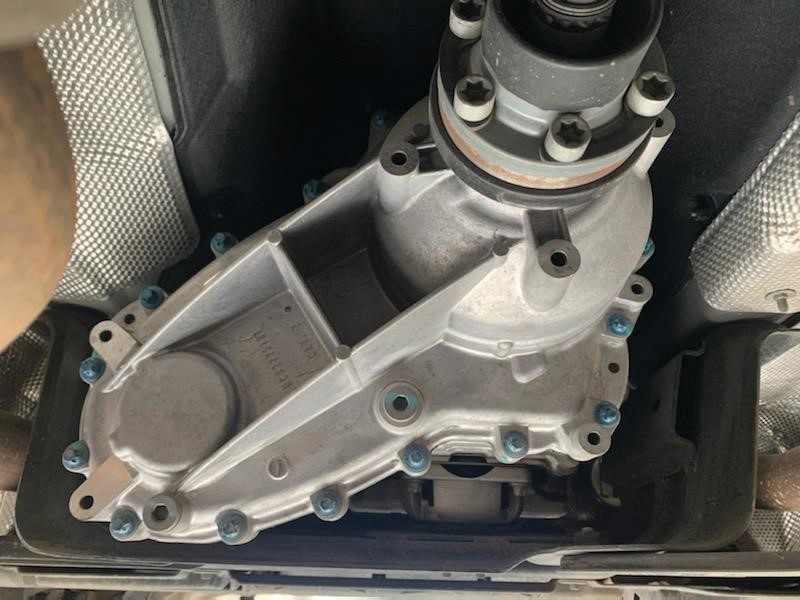
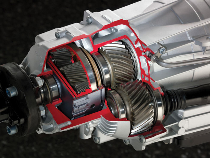
The transfer case in these models is attached directly to the automatic transmission, without an intermediate flange, forming a single drive unit with the engine and front axle gear. The transfer case does not have any hydraulic or mechanical differential locks which in turn reduces the weight significantly. An important repair note in servicing these units is when filling the transfer case (either when changing the fluid or replacing the transfer case unit) be sure to fill the transmission to the bottom of the filler opening, test drive the vehicle and then recheck and top up as necessary. The reason is, the chamber in the front housing section of the transfer case where the planetary gear is located is supplied with oil only when the transfer case is in operation. Don’t neglect this step or you will run the risk of having an inadequate fluid level.
The newer the model you are servicing, the more important it will be to consult the proper workshop literature in regards to servicing transmissions and differentials in a 4MATIC model. This is evident for example in Star Bulletin S-B-00.20/102a, which explains that in the specified models, the ASSYST system does not indicate rear differential fluid changes. The bulletin provides additional details on when and with which fluid the service should be carried out. Missing something like this might cause you to miss not just the need for maintenance, but a chance to sell that maintenance to your customer. In some ways, a WIS subscription can help pay for itself.
The Latest Generation and What the Future Holds
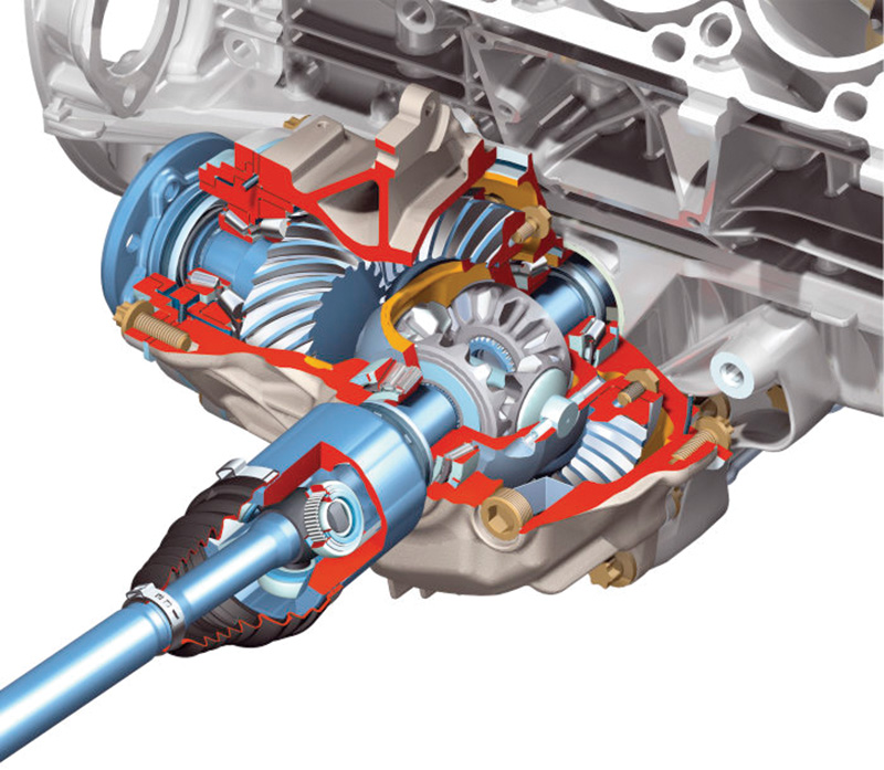
In the S-Class 4MATIC models, the torque to the driven front wheels is provided via a transfer case which requires no additional installation space as it is integrated in the 7G-TRONIC automatic transmission. From there, a driveshaft supplies the power to the front axle. From the front differential, power is transmitted to the front left axle shaft using an intermediate shaft running through an encapsulated shaft channel in the engine oil sump.
The transfer case has an extremely compact design. Mercedes-Benz engineers dispensed with one complete gear stage and, by integrating the rear universal joint in the output gear, it is possible for the drive shaft to the front differential to run very close to the automatic transmission. With these design changes there is no need to have floor design changes as compared to conventional rear wheel drive models.
The Mercedes-Benz all-wheel drive line-up currently encompasses dozens of passenger car models across nearly every model series. Besides the many SUV models, each of the sedan, coupe and wagon variants generally include a 4MATIC version. With all these models on the road you should be well versed in the various phases of 4MATIC as you will be servicing them for years to come.


0 Comments