
Anyone working on Mercedes-Benz cars will recognize the 1996-2002 Model 210 E-Class as a true classic, with millions produced worldwide and many still showing up for maintenance and repair. In this continuing series of articles on Classic Mercedes-Benz models, we will take a closer look at the 210 chassis climate control system and its self-diagnostic capabilities. Essentially the same system was used throughout production, but to ensure consistency everything here will be based on the 2001 model year version.

Warnings
Before we get started, a comment about safety and environmental regulations: You must not work on a refrigerant system without being trained on, and fully understanding, the dangers involved. Escaping refrigerant can freeze skin and cause respiratory distress, causing injury and death. Be sure to use proper personal protective equipment. You must also have a way of safely and properly reclaiming refrigerant. Releasing refrigerant to the atmosphere is a Federal offense in the United States punishable by up to $27,500 per day per violation and can include jail time. If you don’t have a way to safely and properly reclaim the refrigerant, find someone who does, as getting caught (informants can get a $10,000 reward) just isn’t worth it. Please be safe and do the right thing.
The Basics
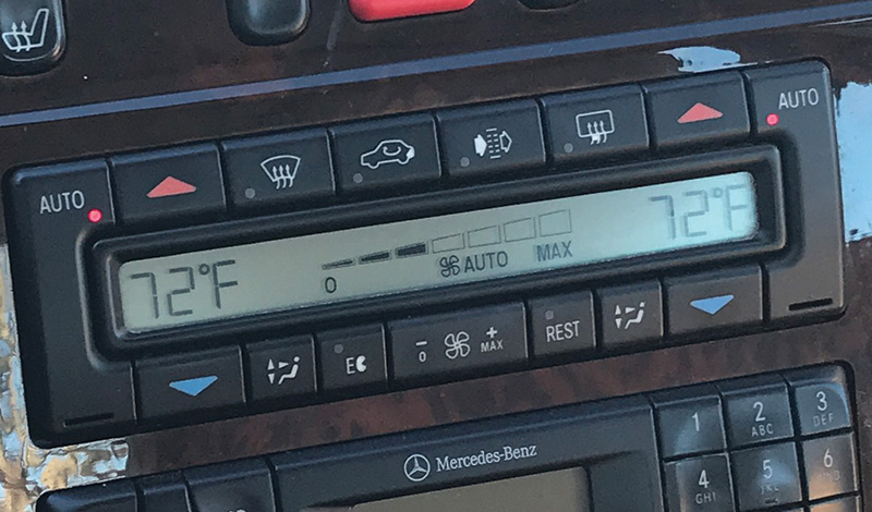
The climate control system is electronically-controlled by the in-dash controller and display, with the flaps actuated by vacuum. The passenger and driver can set different temperatures, but of course there is a limit to how different the temperatures can be within the passenger cabin. Air ducts lead to the rear of the center console and to the rear seating foot wells, in addition to the expected dash and under-dash vents. Standard is the REST feature, which allows the use of residual engine heat to keep the cabin warm (or cooler using circulated air) for up to 30 minutes after the engine is switched off.
There are two sets of filters, one behind the glove box to filter dust from incoming air, and another in the passenger foot well to remove odors using activated charcoal. Unlike the model 124 predecessor, the blower motor is easily accessible in the passenger foot well. The in-car temperature sensor is located within the upper control panel, near the sunroof switch. There is a sun sensor in the center of the dashboard – not easily replaced – that modifies the blower speed slightly to account for sun load. An air quality sensor at the intake ducting detects external pollutants (such as diesel exhaust) and switches the system to Recirculate mode temporarily as needed.
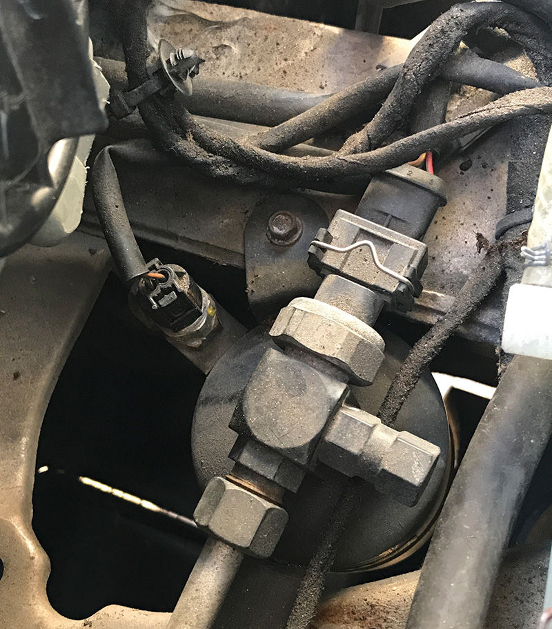
The heating system uses a duo-valve, accommodating the dual temperature controls, and an auxiliary water pump in the engine compartment to help coolant flow through the heater core. The washer fluid reservoir is heated by a coolant circuit also from the auxiliary pump. The air conditioning compressor is a traditional belt-driven type with a magnetic solenoid clutch. A thermostatic expansion valve regulates the flow of refrigerant to the evaporator.
Self-Diagnosis
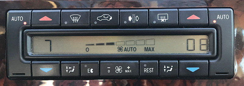
With the ignition on (ideally with the engine running), pressing and holding the REST button for several seconds starts the self-diagnosis display. Although the Mercedes-Benz diagnostic manual (DM, available in Star TekInfo) states to set both temperature displays to 72°F (or 22°C in early models), we have found this to be unnecessary. There are about a dozen and a half different parameters that can be read out using this system, and we will explain what each one means.
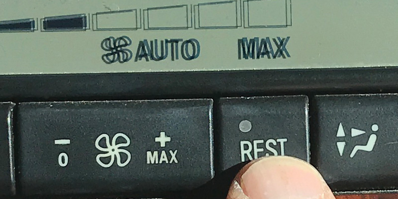
In the self-diagnosis mode, the parameter number appears on the left side of the display, and the actual value is displayed on the right side. You scroll forward through the parameters using the left ‘auto’ button, and backwards using the right ‘auto’ button. After reaching the last parameter, the display moves back to the first one again. To exit self-diagnosis mode, press REST again or switch off the ignition.
Display Code 1 is the in-car temperature sensor (B10/4) reading in the same temperature units as seen by the customer (Fahrenheit or Celsius). If not a close match to the actual interior temperature, test the sensor itself for resistance: At 20°C (68°F) you should measure between 11.9kΩ and 13.0 kΩ. Also verify that the tiny aspirator motor, which draws cabin air over the temperature sensor, runs by supplying 12 volts. If OK, check the wiring according to the Star Wiring diagram.
Display code 2 is the outside temperature sensor (B14), which also supplies the instrument cluster. This sensor is located in the front bumper on the left side. If this doesn’t agree with the instrument cluster, suspect a wiring issue on the K1 line from the instrument cluster.
Display codes 3 and 4 are the heater core temperature sensors (B10/1) for the left (code 3) and right (code 4) heater cores. You can expect these to be different (cooler) from the engine coolant temperature (unless full heat is being called for) since they are regulated by the duo-valve. The sensor has two sensing elements (left and right) with the same specs: at 20°C (68°F) each should read between 11.9kΩ and 13.2kΩ, and at 45°C (113°F) between 4.2kΩ and 4.6kΩ. Be sure to check both sides.
Display code 5 is the evaporator temperature sensor (B10/6). This sensor should read just above 0°C (32°F) with the air conditioning running. This sensor isn’t particularly trouble-prone, but could generate a customer complaint of poor cooling and low air flow if it has failed. Measure the sensor if necessary: 3.2kΩ at 20°C is normal.
Display code 6 is the engine coolant temperature sensor, B11/4. As with the outside temperature sensor (display code 2) the engine coolant temperature, displayed on the instrument cluster gauge, is received by the climate control system from the instrument cluster via the K1 line. As before, if this doesn’t agree with the instrument cluster, suspect a wiring issue.
Display code 7 is the value reported by the refrigerant pressure sensor (B12) located on the receiver-drier just behind the left headlamp. The values are reported in Bar (1 Bar = 14.7 PSI). The pressure sensor needs to have a 5-volt (± 0.25 V) power supply to return a reading. If this sensor has failed, you’ll need to evacuate the refrigerant to replace it. This sensor value may be the most useful reading you can get, since it can confirm an over- or under-charge of refrigerant. We’ll get into the details in a moment in the Diagnosis section.
Display code 8 is the refrigerant temperature sensor (B12/1) also located on the receiver-drier. Measure the sensor resistance and estimate the temperature of the refrigerant it is reading. At 20°C (68°F) the sensor should read less than about 13kΩ, at 40°C less than about 5.5kΩ and at 70°C less than about 1.8kΩ. If the measured values seem reasonable, check the wiring before condemning the sensor.
Display code 10 (9 is not used) is the blower control voltage, which can vary from about 0.8 volts to about 6 volts (displayed as 08 and 60, respectively). If the climate control unit (N22) is delivering the correct voltages to the blower motor controller, but the fan isn’t operating correctly, it could be the fan motor, the controller, or wiring. Again, we’ll discuss this in Diagnosis in a moment.
Display code 11 is the emissions sensor (B31) voltage. Normally this will vary between 4 and 6 volts, but as this only affects recirculation operation, it is rare that anyone would notice a malfunction. In other words, your customer didn’t show up because this sensor failed.
Display code 12 is the sun sensor (B32), which can nudge the blower speed up a bit to compensate for sun load. Expect to see voltages from 0 (dark) to about 4.5 volts (full sun) but, as with the emissions sensor, a malfunction would generally not be noticed by a customer.
Display code 20 (13-19 are not used) displays the control current for the auxiliary fan motor (M4) located behind the radiator. To test, exit test mode and switch the ignition on (engine off). Monitor the voltage at pin 16 on N22x2 (ground the other voltmeter lead). Press both AUTO buttons to command the auxiliary blower motor to run, but for not more than 10 seconds. The voltage should be greater than 2.0 volts and the motor should run. Switch the ignition off. A failed test indicates a fault in the wiring, N65 (the controller, near the left front fog lamp), N22 or the fan motor itself. Perform some diagnostics on N65 by measuring voltages before replacing anything. Note that some later models use CAN via the front SAM for this.
Display code 21 is the engine speed (x100 RPM), received from the instrument cluster via the K1 line.
Display code 22 is the vehicle speed in km/h. The climate control system uses this to reduce blower speed at higher vehicle speeds, compensating for the ram air effect that occurs. Again, this comes via K1 from the instrument cluster.
Display code 23 is the Terminal 58d (ambient lighting) voltage as a percentage of battery voltage. If the lights in N22 are not working, but the bulbs are OK, use this to verify that circuit 58d is being received. This value is adjusted via the instrument cluster.
Display code 24 is the battery voltage in volts, as seen by N22. If this seems abnormal, check the wiring carefully for voltage drops on both the power and ground wires.
Display codes 40 and 41 (all the rest are unused) show the software and hardware version of the climate control controller, and is not very relevant for diagnosis.
Diagnosis
Of course, a Mercedes-Benz Hand-Held Tester was (and still is) the best instrument for diagnosis, but these are quite rare today. Many aftermarket testers can read the system fairly well, but the vast majority of problems can be properly diagnosed with the self-diagnostics, a wiring diagram, and a multimeter.
Looking at display code 7 (refrigerant pressure) we can expect to see a high-side value of about 5 bar with the system and vehicle at ambient temperature. In operation, values typically range from about 9 bar to 15 bar, with higher pressures seen when cooling demands are high. Really low system pressure will cause the EC light in the control unit to light, and the compressor cannot be engaged. If you find that the passenger side vents have cooler air than the driver side vents, it indicates the refrigerant is just a bit low, likely from a slow leak.
In any case, leaks need to be identified and repaired. Evacuate the system and take note of how much refrigerant was recovered. Compare that to the A/C label under the hood, which shows the quantity of refrigerant needed. Find the cause for any discrepancies.
Display code 10 can help diagnose blower fan issues, which can have several causes. In these older models, we almost always find a failed motor as the cause of blower complaints. Remove the motor, located above the passenger foot well, and apply 12 volts directly to the motor on the bench. (Be careful, the motor will ‘jump’ violently. Clamp it securely and stay away). Check this several times to see if there’s a dead spot in the motor. If it spins ferociously, then check the voltage being delivered to the motor controller, both the big 12 volt wiring and the smaller control wire, at the connector near the passenger door hinge area. Compare the control wire voltage to display code 10, they should agree.
Replacing the blower motor is fairly easy, but be aware there are two versions, and only the later version is available now. The early version has a motor controller with several metal ‘spines’ used to dissipate heat, while the newer version does not. If the older version controller or blower fails, you’ll need to buy both. Aftermarket components are available, but we’ve never had good luck with them.
Leaks
If you suspect a leak in the refrigerant circuit, the first task should be to sniff as much of the system as can be accessed using a refrigerant detector. It may be necessary to add some refrigerant if the system is extremely low or empty. Modern refrigerant detectors are reasonably priced and very sensitive.
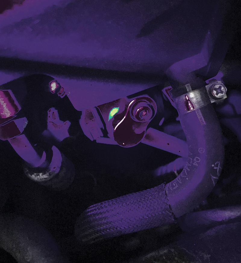
If the sniffer doesn’t find the leak, which sometimes happens with very small leaks, a good approach is to evacuate and recharge the system, adding some leak detection dye. For many years Mercedes-Benz did not approve dye for this purpose, but in the last 20 years some models were even factory-charged with dye. Be sure to scan the system carefully with your ultraviolet lamp before charging, and clean off all dye residue that might be present from previous diagnostic attempts.
With the system clean and charged, send your customer off with a request they return in a few days, and carefully scan the system again to find the leak. Be sure to check the evaporator drain hoses.
Big leaks will be seen on a vacuum test: Pump the system down to vacuum and let it hold for at least half an hour. If the gauge moves, there’s a leak.
Old-school Diagnosis
Finally, any air conditioning system’s refrigerant circuit can be accurately diagnosed using refrigerant pressure gauges. While there’s simply not enough space in StarTuned to deliver a comprehensive A/C theory of operation and diagnosis guide, some basics are in order.
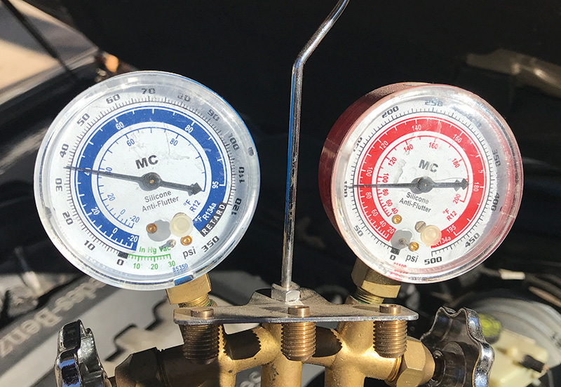
Two gauges are usually used for system diagnosis, one on the low-pressure side and one on the high-pressure side. These are connected to the ports at the driver’s inner fender (low-side) and at the condenser (high-side). At rest, both gauges should read the same, with the pressure roughly corresponding to the system temperature (gauges have ‘temperature’ markings along with pressure). If these are both low, it is an indication of low charge, while if these are high, the system could be overcharged. In both cases, use your A/C machine to evacuate the system and measure the quantity recovered.
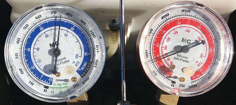
A ‘normal’ reading for high- and low-side with the compressor operating depends on several factors, but are generally about 250 PSI for the high-side and 20 PSI for the low-side. Check the Mercedes-Benz diagnostic manual and Workshop Information System (WIS) for performance charts and tables to calculate what is normal.
With the compressor engaged, low refrigerant is indicated by low readings on both gauges, with the low-side approaching vacuum. If the high-side reading is low while the low-side is not, the compressor might be faulty.
If both readings are normal at first, but then the high-side rises above normal and the low-side drops, this indicates moisture has entered the system and is icing up. If both readings are high, the system is likely overcharged. In the case where pressures are normal, but cooling performance is poor, it could indicate that there is excessive refrigerant oil in the system.
In closing, we hope that this overview of the self-diagnostic capabilities of the model 210 E-Class was useful. Just knowing how to get into the system and what each code means can make diagnosis easier. The basic test values included should help in finding a faulty component or sensor. With summer fast approaching, we are starting the busy season for air conditioning repairs, and our goals are aligned with yours: Happy customers.


0 Comments