

A clear wiring schematic is your best friend when tracking down LIN faults
Old school versus new school
The quote from Aristotle serves as a reminder and the bitter taste of what happens when you don’t pay attention to modern technology. This is the story of a modern network vehicle that had existing problems with headlamps, fog lamps, signal lamps, and windshield wipers. The story also continues with an acquaintance that isn’t winning the battle with technology that is not clearly understood or previously encountered. Now it’s a combined meeting with the Lancer and how this isn’t about the encounter, but the message of education. The modern technician must evolve in modern technology. Keep it simple.
| Tools Used | |
|---|---|
| Launch EasyDiag | 90 amp power supply |
| Android 2 channel oscilloscope | Android tablet |
| Multimeter | Camera, pen, paper, highlighter |
| Current schematics and relevant TSBs |
History
This particular request came about as a rather simple question about the customer complaint of non operating components on both sides of the steering wheel. Both sides means, each attached stalk at the steering column for: headlamps (high and low beams), turn signals, and intermittent wiper.
Unfortunately my compatriot decided to carefully open the harness, and test the under hood fuse panel and ETACS module. That decision was based on old school theory and not having the knowledge base of how this system works. Despite having current schematics and assumptions, â€olde school†testing proved fruitless. The lesson here is about the LIN (Local Interconnect Network) and keeping it simple.
Theory of operation
The LIN system is an inexpensive serial network protocol. LIN is used for communication between components, and those components can also be called “slave modules.†The LIN modules are relatively simple modules controlling devices such as wiper motors, sun roofs, windows, heater motors, seat position, mirror control, cruise control, climate control, etc. LIN operating voltage is 12 volts using low-cost 8-bit microcontrollers. Regard LIN as a master/slave communication protocol on a single wire. The LIN system allows for lighter wiring systems/harnesses and switching assemblies.
Therefore LIN communication is able to control sub modules via single wire messages and to detect defective nodes. LIN devices are also required to enter sleep mode to potentially conserve system power.
Test and note 1
All window operations and sunroof operations worked perfectly. The security locking system worked normally. The remote key fob was active within the vehicle. A LIN failure allowed the wipers to operate at full speed only.
Step 1
We began with a complete scan and used it as the baseline for the repair. We cleared all faults and captured/saved all new scans. It was important to pay attention to any future changes, faults, and oscilloscope images.
| System Name | State |
|---|---|
| MPI/GDI/Diesel | No Fault Code |
| ABS (Anti-Lock Braking System) | No Fault Code |
| SRS-Air Bag | No Fault Code |
| AC (Air Conditioning) | No Fault Code |
| KOS/Immo/Keyless | Find Fault Code | 7 |
| TPMS (Tire Pressure Monitoring System) | Find Fault Code | 7 |
| Meter | No Fault Code |
| ETACS | Find Fault Code | 1 |
| LIN | No Fault Code |
| Audio | No Fault Code |
| OCM | No Fault Code |
| Fault Code | Details | State | System Name |
|---|---|---|---|
| U1515 | No Bus Activity Error for LIN | Active | ETACS |
Description
The manufacturer description is, “The ETACS-ECU will set DTC U1515 when no communication has been carried out for more than a certain period after the slave task received last valid data.â€
Step 2
We attempted to acquire the factory schematics (or compatible) and in this case, they provided fruitful information. We also researched any TSBs associated with the fault and any information that pertained to test procedures for the LIN system.
Step 3
It was helpful to lay out the complete schematic and highlight the controllers/switches that were in question, then physically test any system or controls that were associated with the ETACS module using the LIN bus. We noted what was or was not working. This is the process of elimination.
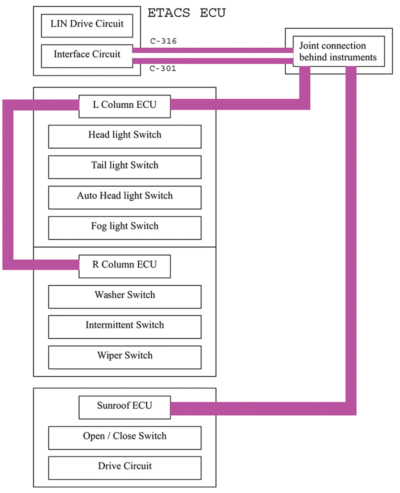
To the right is a simplified diagram made with MS Word and Photoshop. Follow details in this article by searching and printing all the required schematics. Use a highlighter to indicate the controls for this model.
The LIN connection (wiring) is violet for this Lancer and the ETACS is the master control unit.
Both the left stalk and right stalk ECUs are internally connected to LIN.
Both left and right stalks share internal B+ and B- connections. One LIN connection is provided to the left stalk.
The sunroof ECU LIN wiring is connected to a joint connection behind the instrument cluster with the left and right ECU stalks at the steering wheel. The sunroof ECU connection continues from the joint connection to the ETACS module connection C-316.
We wanted to keep these tests simple; removing the instruments to access the joint connection was not appealing and was overly complicated.
Test and note 2
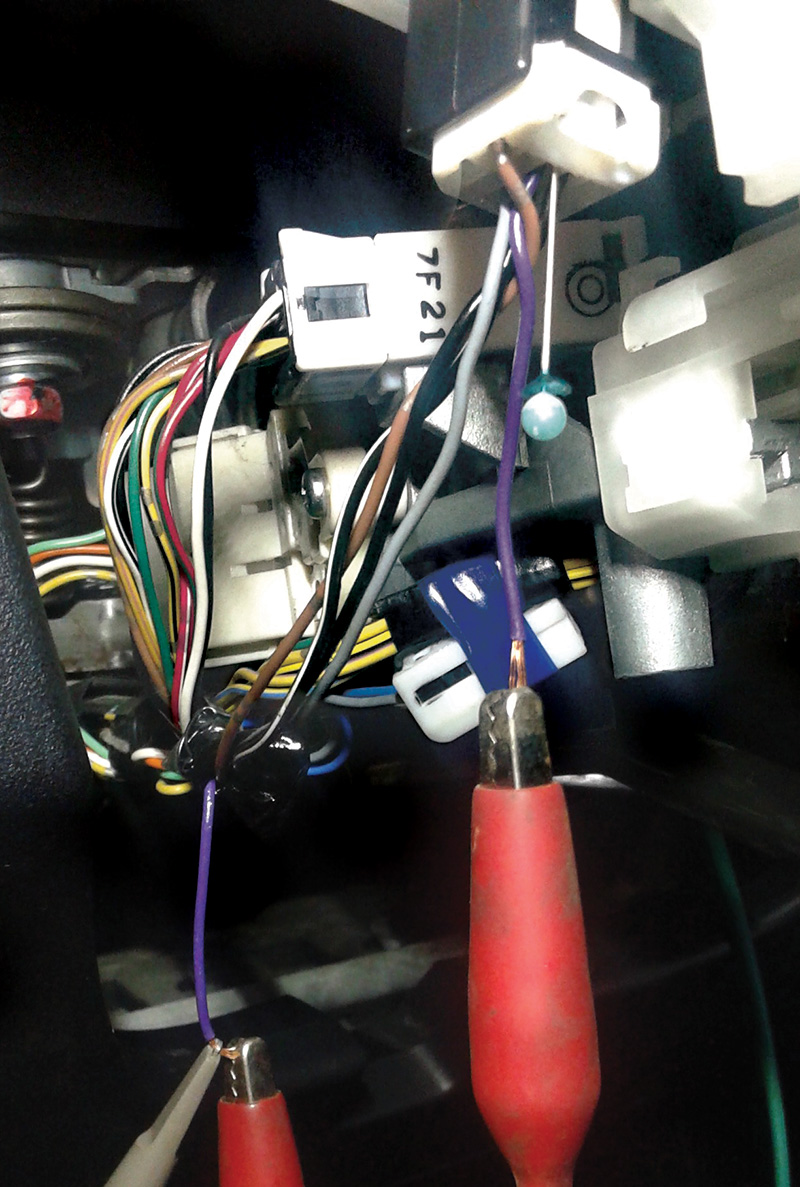
For the sake of simplicity and recording non true or unsubstantiated oscilloscope images, the decision was made to cut one wire to the main stalk (violet) and measure the LIN messages while moving each stalk in all positions. The schematic provided one fact: each stalk control had its own microcontroller and that meant “output†from the headlamp, turn signal, and wiper switches.
The image indicates the cut violet wire and the connection that can be used with the oscilloscope. A jumper wire can also be a quick solution to open or close the LIN connection to move between tests. The “sewing needle†also becomes useful for probing these smaller diameter harnesses.
Step 4
We experimented with the one subsystem that was not operating. In this case, the modules were connected at the steering wheel and noted all the LIN modules were connected by viewing the schematics. Within this specific issue, and using the multiple schematics, brought forward the theory that part of the LIN system was damaged, non communicating, or exhibiting a communication disturbance. This connection is directly at the stalk with the LIN wire disconnected (cut).
| NOTE: The correct repair is NOT solder; use “crimp and shrink†or a crimp barrel with high quality shrink tube. |
Step 5
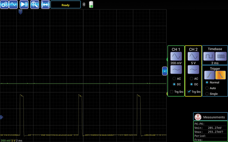
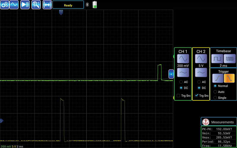
We attached the oscilloscope at the stalk LIN bus and looked at the image. Normal LIN “chatter†is quick with many messages and this was not the case. As an experiment to see how the stalks send messages, at the cut wire, we looked at those messages while operating each stalk. We attached the second channel to view LIN messages. The yellow image was zoomed in with a repeating “three points†(very brief and two in view) every time any switch position was moved or manipulated. This should mean the microcontroller was trying to send a message. The green pattern is of the cut wire and was not expected. The message appeared not consistent with LIN message structure. All the messages were saved and noted.
Step 6
Now if you encounter a similar problem, look at the schematics; is there another junction or parallel connection to another LIN system? If so, disconnect that system and measure the LIN message at the open connection of the cut wire (not the stalk connection). Is there a difference in the messages with opening or closing the ETACS connection C-316? Try the same test with the multimeter. Note all the values.
If LIN chatter is normalized, reconnect the cut wire and test the stalks again. Measure the connection again with the oscilloscope and multimeter. Note those values.
| NOTE: Connection C-316 is at the ETACS module and is a direct connection to the sunroof controller. C-316 should carry the LIN messages with B+ and B-. |
| NOTE: A multimeter will offer values but never the true picture. Using any of the searched TSBs may offer a value but doesn’t offer the image of LIN chatter. As useful as a TSB is, take that information with a grain of salt. |
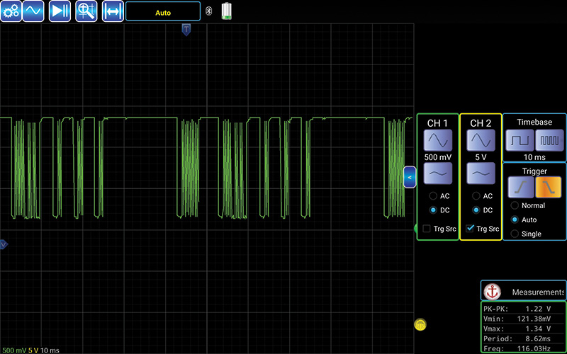
The final repair and the image is what should be expected and if paying attention, moving each stalk will show a slightly different pattern within the LIN message.
| Note (!): It can take one damaged LIN node(s) to “shut down†or disrupt a LIN network. |
In this situation, disconnecting the sunroof control harness at the ETACS module C-316 resulted in the perfect LIN message structure (you could reconnect the cut wire to test).
The modules and operation at both stalks were all back to normal. Recording the LIN waveform and reconnecting the harness connection C-316 shut down the stalk communication and resulted with an unfavorable LIN message structure.
With the schematic, the sunroof control also has a microcontroller and the final proof is to disconnect that specific module and measure the violet harness between those points, the result being the harness is intact and not shorted to positive or negative.
Go back and read the note above
This shop and customer opted for a used sunroof controller and it worked perfectly. The LIN messages were stable and all controls at the steering column worked as intended. The final test was to reattach the original sunroof controller and notice the change.
What was learned?
- Understand the systems before plowing through a wiring harness.
- Access a wiring harness schematic that fits the model and system.
- Cut and tape the schematics together in a logical order.
- Use a highlighter to determine LIN communications with B+ and B-.
- Use an oscilloscope to measure messages.
- Use a multimeter to test supply voltages and ground connections.
- It takes one defective LIN controller (node) to disturb a LIN network.


0 Comments